6-133
6
Related Parameters
Multi-function Digital Inputs (H1-01 to H1-05)
Adjusting the HSB Deceleration Frequency Width (n3-01)
This parameter sets the step value that is used for lowering the output frequency to achieve a large negative
slip and thereby to brake the motor.
Normally no adjustments is necessary. Increase the value if a DC bus overvoltage faults occur.
Adjusting the HSB Current Limit (n3-02)
The setting of parameter n3-02 limits the output current while high slip braking is active. The current limit
affects the achievable deceleration time.
The lower the current limit the longer is the deceleration time.
Setting the HSB Dwell Time at Stop (n3-03)
At the end of a high slip braking the output frequency is held at the minimum output frequency for the time set
in n3-03. Increase the time if the motor coasts after HSB.
Setting the HSB Overload Time (n3-04)
n3-04 sets the HSB overload time. If the output frequency does not change for any reason although an HSB
command is given, an OL7 fault will be displayed and the fault output will operate.
Activating High Slip Braking
If one of the multifunction inputs is set to “68” it can be used to activate the HSB function. The inverter will
brake the motor immediately after the HSB command was given. HSB cannot be stopped, i.e. normal inverter
operation cannot be resumed.
The HSB function is activated by a pulse signal, a continuous activating of the digital input is not necessary.
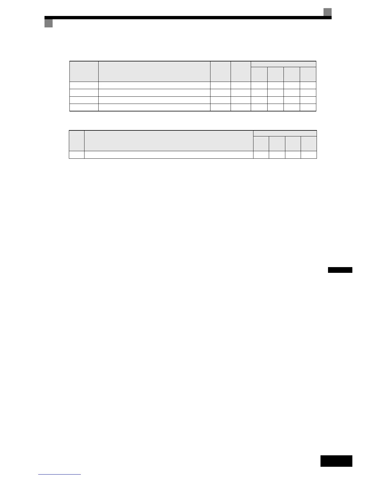
Parameter
No.
Name
Factory
Setting
Change
during
Opera-
tion
Control Methods
V/f
V/f with
PG
Open
Loop
Vector
Closed
Loop
Vector
n3-01 High-slip braking deceleration frequency width 5% No A A No No
n3-02 High-slip braking current limit 150% No A A No No
n3-03 High-slip braking stop dwell time 1.0 s No A A No No
n3-04 High-slip braking OL time 40 s No A A No No
Set
Value
Function
Control Methods
V/f
V/f
with
PG
Open
Loop
Vector
Closed
Loop
Vector
68 High Slip Braking command (ON: HSB activated) Yes Yes No No
 Loading...


