CYLINDER HEAD
Name Torque in Nm
Spark plug 12 ÷ 14
Nuts fixing head to cylinder (1) (^) 9 ÷ 11 + 180°
Head fixing side screws 11 ÷ 12
Starter ground screw 7 ÷ 8.5
M5 side screw locking washers on camshaft 7 ÷ 8.5
Tappet set screw lock nut 6 ÷ 8
Timing chain tensioner slider screw 10 ÷ 14
Starter ground support screw 11 ÷ 15
M6 central screw locking washers on camshaft 11 ÷ 15
Timing chain tensioner support screw 11 ÷ 13
Timing chain tensioner central screw 5 - 6
Camshaft retention plate screw 4 ÷ 6
TRANSMISSION
Name Torque in Nm
Belt support roller screw 11 ÷ 13
Clutch unit nut on driven pulley 45 ÷ 50
Drive pulley nut 75 ÷ 83
Transmission cover screws 11 ÷ 13
Driven pulley shaft nut 54 ÷ 60
Rear hub cover screws 24 ÷ 27
FLYWHEEL
Name
Torque in Nm
Flywheel cover fixing screws 5 - 6
Stator assembly screws (°) 3 ÷ 4
Flywheel nut 52 ÷ 58
Pick-Up clamping screws 3 ÷ 4
Screw fixing freewheel to flywheel 13 ÷ 15
CRANKCASE AND CRANKSHAFT
Name
Torque in Nm
Internal engine crankcase bulkhead (transmission-side half
shaft) screws
4 ÷ 6
Engine-crankcase coupling screws 11 ÷ 13
Starter motor screws 11 ÷ 13
Crankcase timing system cover screws (°) 3.5 ÷ 4.5
COOLING
Name
Torque in Nm
Water pump rotor cover 3 ÷ 4
Screws for water pump rotor driving link 3 ÷ 4
Thermostat cover screws 3 ÷ 4
Bleed screw: 3
(°) Apply LOCTITE 242 medium-strength threadlock
(*) The two screws must be tightened to the prescribed torque after having done so with the rear wheel
axle nut. Safety locks: see "Pre-delivery operations".
(^) Fasten the nuts in two crossed passes.
(1) Before fitting the nuts lubricate them with engine oil
Overhaul data
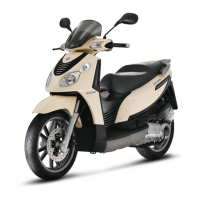
Characteristics Carnaby 125 - 200
CHAR - 16
 Loading...

