R8C/20 Group, R8C/21 Group 12. Interrupts
Rev.2.00 Aug 27, 2008 Page 94 of 458
REJ09B0250-0200
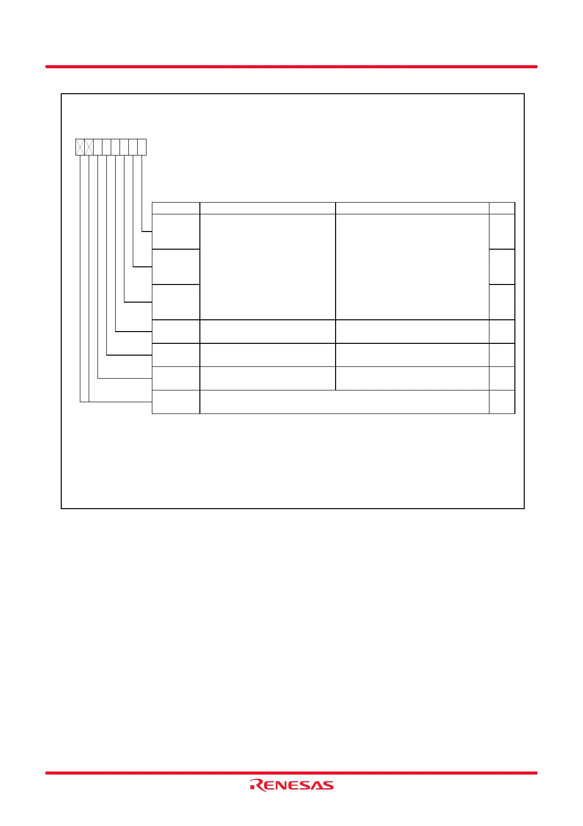
Figure 12.5 Registers INT0IC to INT3IC
INTi Interrupt Control Register (i = 0 to 3)
(2)
Symbol Address After Reset
INT2IC
0055h XX00X000b
INT1IC
0059h XX00X000b
INT3IC
005Ah XX00X000b
INT0IC 005Dh XX00X000b
Bit Symbol Bit Name Function RW
NOTES:
1.
2.
3.
4.
To rew rite the interrupt control register, rew rite it w hen the interrupt request w hich is applicable for its register is not
generated. Refer to
12.6.5 Changing Interrupt Control Register Contents
.
If the INTiPL bit in the INTEN register is set to 1 (both edges), set the POL bit to 0 (selects falling edge).
The IR bit may be set to 1 (requests interrupt) w hen the POL bit is rew ritten. Refer to
12.6.4 Changing Interrupt
Sources
.
b7 b6 b5 b4 b3 b2 b1 b0
0
ILV L0 RW
Interrupt priority level select bits
b2 b1 b0
0 0 0 : Level 0 (interrupt disable)
0 0 1 : Level 1
0 1 0 : Level 2
0 1 1 : Level 3
1 0 0 : Level 4
1 0 1 : Level 5
1 1 0 : Level 6
1 1 1 : Level 7
ILV L1 RW
ILV L2 RW
IR
Interrupt request bit 0 : Requests no interrupt
1 : Requests interrupt
RW
(1)
POL
Polarity sw itch bit
(4)
0 : Selects falling edge
1 : Selects rising edge
(3)
RW
—
(b5)
Reserved bit Set to 0
RW
—
(b7-b6)
—
Nothing is assigned. If necessary, set to 0.
When read, the content is undefined.
Only 0 can be w ritten to the IR bit. (Do not w rite 1.)
 Loading...