R8C/20 Group, R8C/21 Group 16. Clock Synchronous Serial Interface
Rev.2.00 Aug 27, 2008 Page 312 of 458
REJ09B0250-0200
16.3 I
2
C Bus Interface
The I
2
C bus interface is the circuit which is used for a serial communication based on the data transfer format of the
Philips I
2
C bus.
Table 16.5 lists a I
2
C bus Interface Specifications, Figure 16.22 shows a Block Diagram of I
2
C bus Interface and
Figure 16.23 shows the External Circuit Connection Example of Pins SCL and SDA. Figures 16.24 to 16.31 show
the registers associated with the I
2
C bus interface.
* I
2
C bus is a trademark of Koninklijke Philips Electronics N. V.
NOTE:
1. The interrupt sources can use the only I
2
C bus interface interrupt vector table.
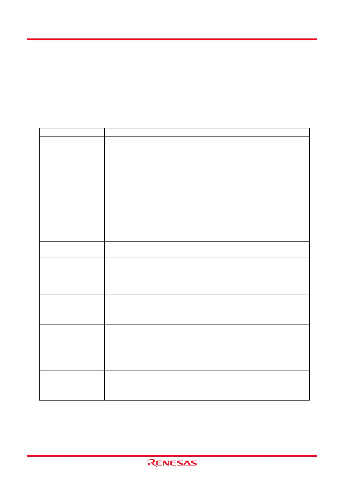
Table 16.5 I
2
C Bus Interface Specifications
Item Specification
Communication
Formats
•I
2
C bus format
- Selectable for master / slave device
- Continuous transmit / receive (since the shift register, transmit data register
and receive data register are independent)
- Start / stop conditions are automatically generated in master mode
- Automatic loading of acknowledge bit when transmit
- Bit synchronization / wait function (in master mode, the state of the SCL
signal is monitored per bit and the timing is synchronized automatically. If
the transfer is not possible yet, stand by to set the SCL signal to “L”.
- Direct drive of the SCL and SDA pins (N-channel open drain output) is
enabled
• Clock synchronous serial format
- Continuous transmit / receive (since the shift register, transmit data register
and receive data register are independent)
I/O Pins SCL (I/O): Serial clock I/O pin
SDA (I/O): Serial data I/O pin
Transfer Clocks • When the MST bit in the ICCR1 register is set to 0
The external clock (input from the SCL pin)
• When the MST bit in the ICCR1 register is set to 1
The internal clock selected by the CKS0 to CKS3 bits in the ICCR1 register
(output from the SCL pin)
Receive Error Detection • Detects overrun error (clock synchronous serial format)
An overrun error occurs during receive. When the last bit of the following data
is received while the RDRF bit in the ICSR register is set to 1 (data in the
ICDRR register), the AL bit is set to 1.
Interrupt Sources
•I
2
C bus format .................................. 6 types
(1)
Transmit data empty (including when slave address matches), transmit ends,
receive data full (including when slave address matches), arbitration lost,
NACK detection and stop condition detection.
• Clock synchronous serial format ...... 4 types
(1)
Transmit data empty, transmit ends, receive data full and overrun error
Select Functions
•I
2
C bus format
- Selectable for the output level of the acknowledge signal when receive
• Clock synchronous serial format
- Selectable for the MSB-first or LSB-first to the data transfer direction
 Loading...