R8C/20 Group, R8C/21 Group 14. Timers
Rev.2.00 Aug 27, 2008 Page 167 of 458
REJ09B0250-0200
14.3.3 Synchronous Operation
The TRD1 register is synchronized with the TRD0 register.
• Synchronous preset
When the SYNC bit in the TRDMR register is set to 1 (synchronous operation), the data is written to both
the TRD0 and TRD1 registers after writing to the TRDi register.
• Synchronous clear
When the SYNC bit in the TRDMR register is set to 1 and the CCLR2 to CCLR0 bits in the TRDCRi
register are set to 011b (synchronous clear), and the TRD0 register is set to 0000h at the same time as the
TRD1 register is set to 0000h.
Also, when the SYNC bit in the TRDMR register is set to 1 and the CCLR2 to CCLR0 bits in the TRDCRi
register are set to 011b (synchronous clear), and the TRD1 register is set to 0000h at the same time as the
TRD0 register is set to 0000h.
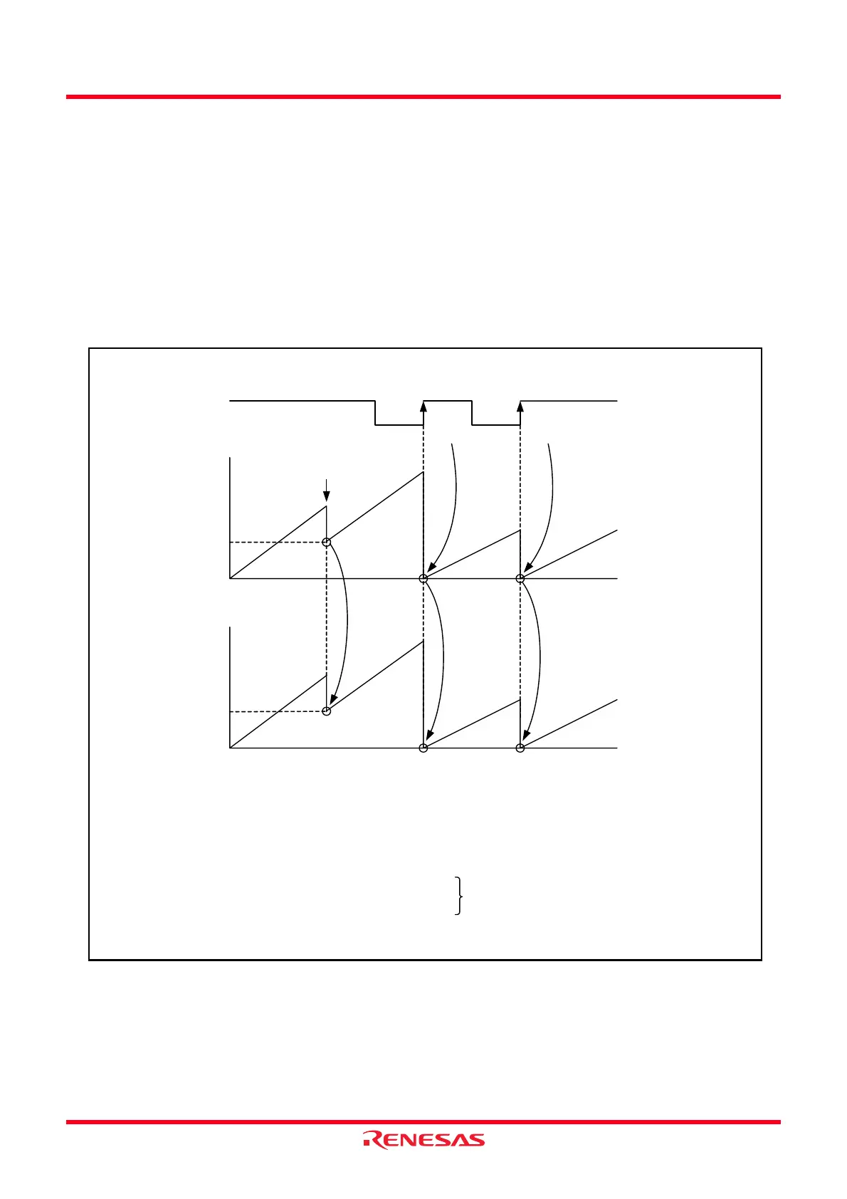
Figure 14.31 Synchronous Operation
Value in
TRD0 register
TRDIOA0 input
n
n is set
n writing
Value in
TRD1 register
n
Set to 0000h with TRD0 register
Set to 0000h by input capture
The above applies to the following conditions:
• The SYNC bit in the TRDMR register is set to 1 (synchronous operation).
• The CCLR2 to CCLR0 bits in the TRDCR0 register are set to 001b (set the TRD0 register to 0000h in input capture).
The CCLR2 to CCLR0 bits in the TRDCR1 register are set to 011b.
(Set the TRD1 register to 0000h synchronizing with the TRD0 register.)
• The IOA2 to IOA0 bits in the TRDIORA0 register are set to 100b.
• The CMD1 to CMD0 bits in the TRDFCR register are set to 00b. (Input capture at the rising edge of the TRDIOA0 input)
The PWM 3 bit in the TRDFCR register is set to 1.
n is set
 Loading...