R8C/20 Group, R8C/21 Group 14. Timers
Rev.2.00 Aug 27, 2008 Page 249 of 458
REJ09B0250-0200
14.3.11 Timer RD Interrupt
Timer RD generates the Timer RD interrupt request based on 6 sources every channel. The Timer RD interrupt
has 1 TRDiIC register (IR bit, ILVL0 to ILVL2 bits) every channel, and 1 vector.
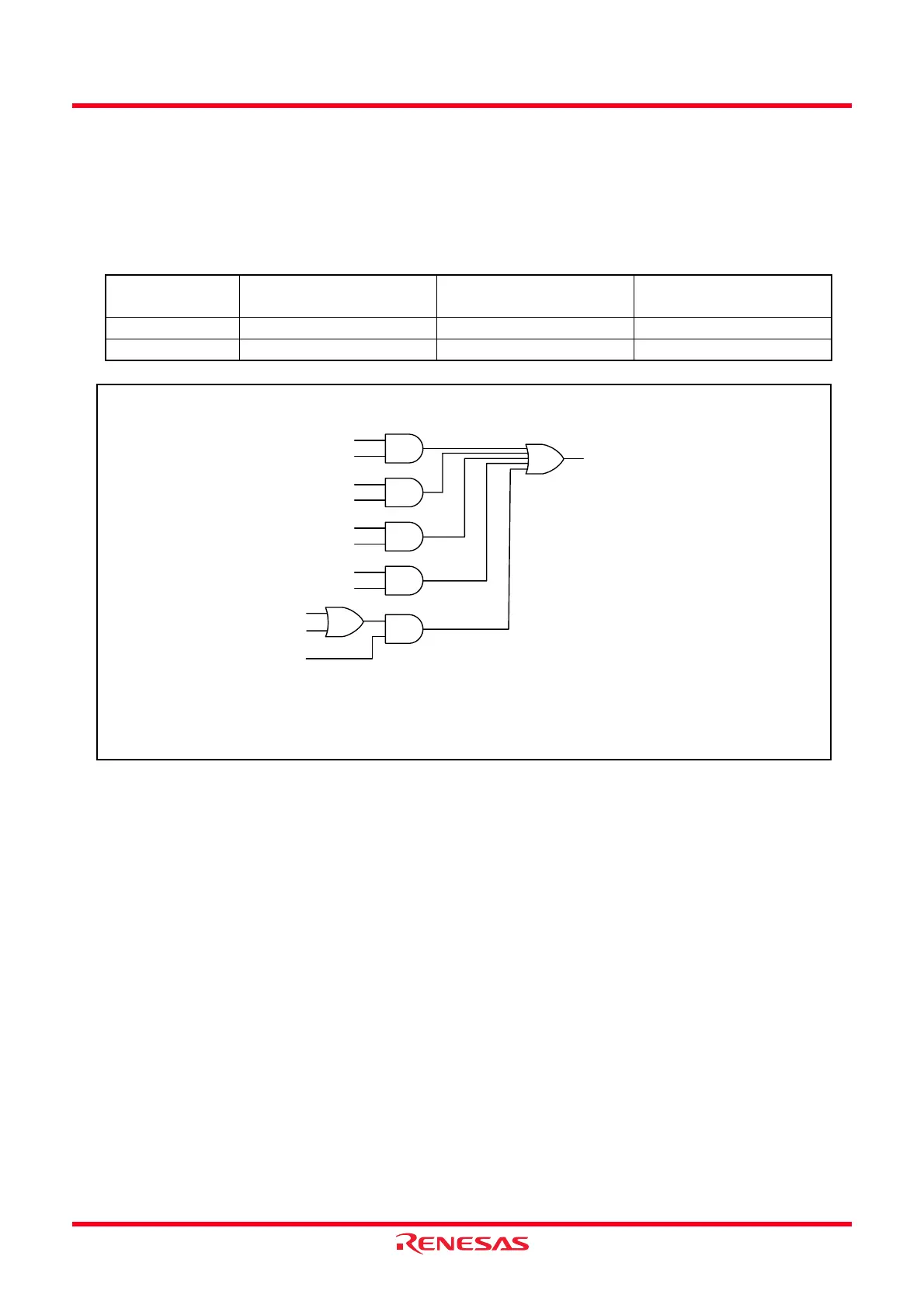
Table 14.35 lists the Registers Associated with Timer RD Interrupt and Figure 14.109 shows the Block Diagram
of Timer RD Interrupt.
Figure 14.109 Block Diagram of Timer RD Interrupt
As with other maskable interrupts, the timer RD interrupt is controlled by the combination of the I flag, IR bit,
bits ILVL0 to ILVL2, and IPL. However, since the interrupt source (timer RD interrupt) is generated by a
combination of multiple interrupt request sources, the following differences from other maskable interrupts
apply:
• When bits in the TRDSRi register corresponding to bits set to 1 in the TRDIERi register are set to 1 (enable
interrupt), the IR bit in the TRDiIC register is set to 1 (interrupt requested).
• When either bits in the TRDSRi register or bits in the TRDIERi register corresponding to bits in the
TRDSRi register, or both of them, are set to 0, the IR bit is set to 0 (interrupt not requested). Therefore,
even though the interrupt is not acknowledged after the IR bit is set to 1, the interrupt request will not be
maintained.
• When the conditions of other request sources are met, the IR bit remains 1.
• When multiple bits in the TRDIERi register are set to 1, which request source causes an interrupt is
determined by the TRDSRi register.
• Since each bit in the TRDSRi register is not automatically set to 0 even if the interrupt is acknowledged, set
each bit to 0 in the interrupt routine. For information on how to set these bits to 0, refer to the descriptions
of the registers used in the different modes (Figures 14.41, 14.56, 14.69, 14.81, 14.92 and 14.104).
Table 14.35 Registers Associated with Timer RD Interrupt
Timer RD
Status Register
Timer RD
Interrupt Enable Register
Timer RD
Interrupt Control Register
Channel 0 TRDSR0 TRDIER0 TRD0IC
Channel 1 TRDSR1 TRDIER1 TRD1IC
Timer RD (channel i)
Interrupt request
(IR bit in TRDiIC register)
IMFA bit
IMIEA bit
IMFB bit
IMIEB bit
IMFC bit
IMIEC bit
IMFD bit
IMIED bit
UDF bit
OVF bit
OVIE bit
i = 0 or 1
IMFA, IMFB, IMFC, IMFD, OVF, UDF: Bits in TRDSRi register
IMIEA, IMIEB, IMIEC, IMIED, OVIE: Bits in TRDIER register
Channel i
 Loading...