R8C/20 Group, R8C/21 Group 14. Timers
Rev.2.00 Aug 27, 2008 Page 248 of 458
REJ09B0250-0200
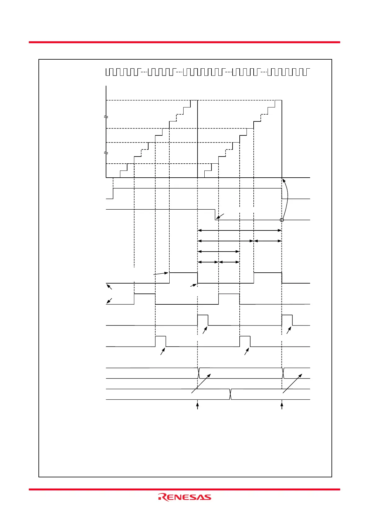
Figure 14.108 Operating Example of PWM3 Mode
Value in TRD0 register
Count source
TRDIOA0 output
0000h
FFFFh
TRDIOB0 output
m: Setting value in TRDGRA0 register
n: Setting value in TRDGRA1 register
p: Setting value in TRDGRB0 register
q: Setting value in TRDGRB1 register
m
n
p
q
TSTART0 bit in
TRDSTR register
1
0
Set to 0 by a program Set to 0 by a program
m + 1
n + 1 m - n
p + 1
q + 1 p - q
Count stop
Output “H” by the
compare match in the
TRDGRA1 register
Set to 0 by a programSet to 0 by a program
Set to 0 by a program
Transfer
m
m Following data
Transfer
m
Output “L” by the compare
match in the TRDGRA0 register
Transfer from the buffer register
to general register
Transfer from the buffer register
to general register
Initial output “L”
j = either A or B
The above applies to the following conditions:
• Both the TOA0 and TOB0 bits in the TRDOCR register are set to 0 (initial output level “L”, output “H” by the compare match in the
TRDGRj1 register, output “L” by the compare match in the TRDGRj0 register)
• The BFC0 bit in the TRDMR register is set to 1 (the TRDGRC0 register is used as the buffer register of the TRDGRA0 register).
CSEL0 bit in
TRDSTR register
1
0
IMFA bit in
TRDSR0 register
1
0
IMFB bit in
TRDSR0 register
1
0
TRDGRA0 register
TRDGRC0 register
 Loading...