R8C/20 Group, R8C/21 Group 10. Clock Generation Circuit
Rev.2.00 Aug 27, 2008 Page 79 of 458
REJ09B0250-0200
10.4.3 Stop Mode
Since the oscillator circuits stop in wait mode, the CPU clock and peripheral function clock stop and the CPU
and peripheral functions clocked by these clocks stop operating. The least power required to operate the MCU
is in stop mode. If the voltage applied to the VCC pin is VRAM or more, the internal RAM is maintained.
The peripheral functions clocked by external signals maintain operating.
Table 10.4 lists Interrupts to Exit Stop Mode and Usage Conditions.
10.4.3.1 Entering Stop Mode
The MCU enters stop mode by setting the CM10 bit in the CM1 register to 1 (all clocks stop). At the same
time, the CM06 bit in the CM0 register is set to 1 (divide-by-8 mode) and the CM15 bit in the CM10 register is
set to 1 (drive capability HIGH of XIN clock oscillator circuit).
When using stop mode, set the OCD1 to OCD0 bits to 00b before entering stop mode.
10.4.3.2 Pin Status in Stop Mode
The status before entering wait mode is maintained.
However, when the CM13 bit in the CM1 register is set to 1 (XIN-XOUT pins), the XOUT(P4_7) pin is held
“H”. When the CM13 bit is set to 0 (input port P4_6 and P4_7), the P4_7(XOUT) is held in input status.
10.4.3.3 Exiting Stop Mode
The MCU exits stop mode by a reset or peripheral function interrupt.
When using a reset to exit stop mode, set the ILVL2 to ILVL0 bits for the peripheral function interrupts to 000b
(disables interrupts) before setting the CM10 bit to 1.
Figure 10.11 shows the Time from Stop Mode to Interrupt Routine Execution.
When using a peripheral function interrupt to exit stop mode, set up the following before setting the CM10 bit
to 1.
(1) Set the interrupt priority level to the ILVL2 to ILVL0 bits of the peripheral function interrupts to use for
exiting stop mode. Set the ILVL2 to ILVL0 bits of the peripheral function interrupts not to use for
exiting stop mode to 000b (disables interrupt).
(2) Set the I flag to 1.
(3) Operates the peripheral function to use for exiting stop mode.
When exiting by a peripheral function interrupt, the interrupt sequence is executed when an interrupt
request is generated and the CPU clock supply is started.
If the clock used immediately before stop mode is a system clock and stop mode is exited by a peripheral
function interrupt, the CPU clock becomes the previous system clock divided by 8.
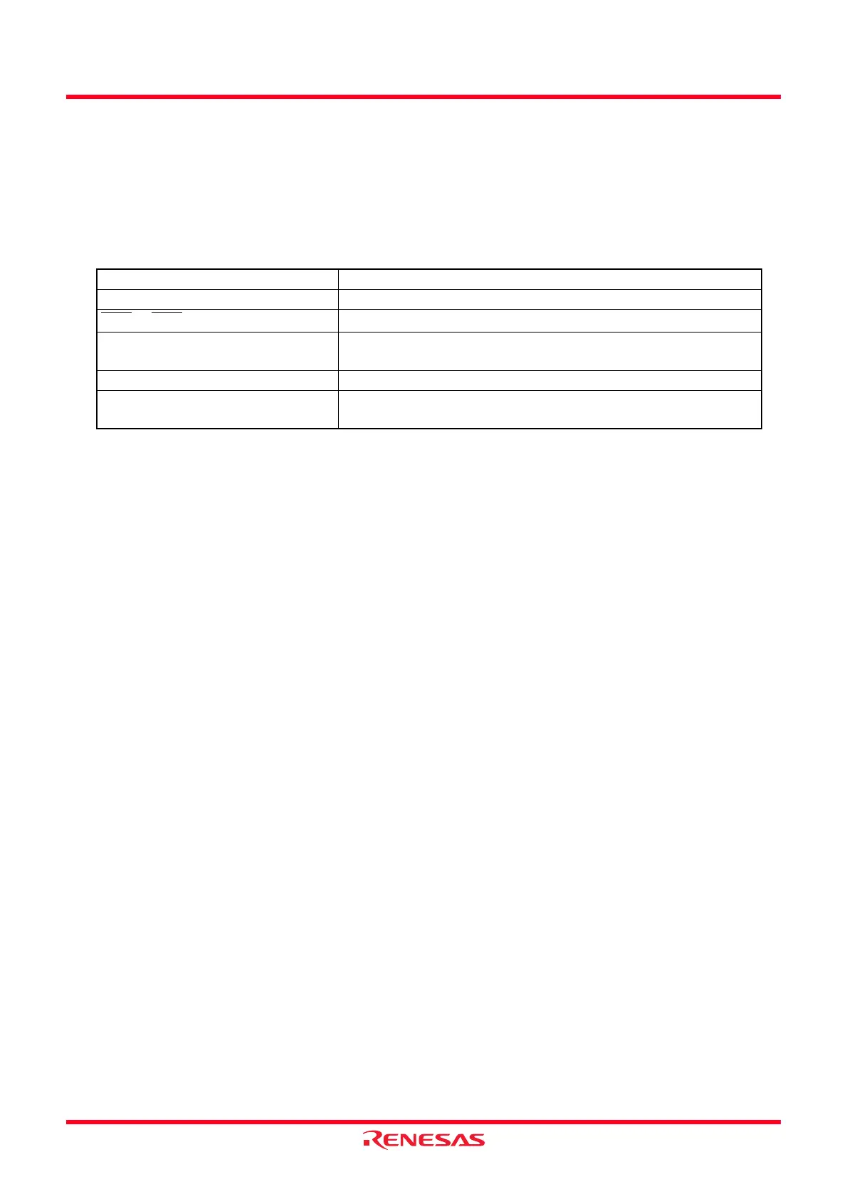
Table 10.4 Interrupts to Exit Stop Mode and Usage Conditions
Interrupt Usage Conditions
Key Input Interrupt −
INT0
to INT3 Interrupt Can be used if there is no filter
Timer RA Interrupt When there is no filter and external pulse is counted in event
counter mode
Serial Interface Interrupt When external clock is selected
Voltage Monitor 2 Interrupt Usable in digital filter disabled mode (VW2C1 bit in VW2C register
is set to 1)
 Loading...