R8C/20 Group, R8C/21 Group 12. Interrupts
Rev.2.00 Aug 27, 2008 Page 92 of 458
REJ09B0250-0200
12.1.6 Interrupt Control
The following describes enable/disable the maskable interrupts and set the priority order to acknowledge. The
contents explained does not apply to the nonmaskable interrupts.
Use the I flag in the FLG register, IPL and the ILVL2 to ILVL0 bits in each interrupt control register to enable/
disable the maskable interrupts. Whether an interrupt is requested is indicated by the IR bit in each interrupt
control register.
Figure 12.3 shows the Interrupt Control Register, Figure 12.4 shows Registers TRD0IC, TRD1IC, SSUIC, and
IICIC and Figure 12.5 shows the Registers INT0IC to INT3IC.
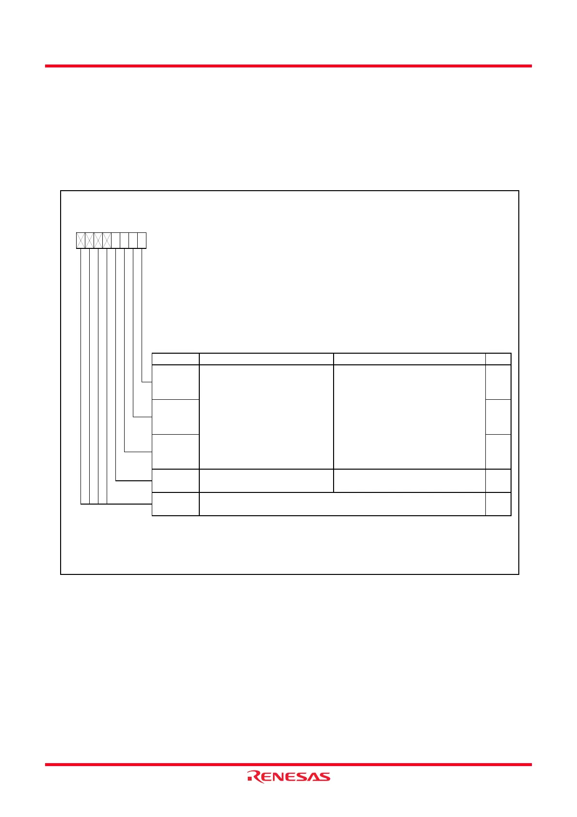
Figure 12.3 Interrupt Control Register
Interrupt Control Register
(2)
Symbol Address After Reset
TREIC
004Ah XXXXX000b
KUPIC
004Dh XXXXX000b
ADIC
004Eh XXXXX000b
S0TIC
0051h XXXXX000b
S0RIC
0052h XXXXX000b
S1TIC
0053h XXXXX000b
S1RIC
0054h XXXXX000b
TRAIC
0056h XXXXX000b
TRBIC 0058h XXXXX000b
Bit Symbol Bit Name Function RW
NOTES:
1.
2. Rew rite the interrupt control register, rew rite it w hen the interrupt request w hich is applicable for its register is not
generated. Refer to
12.6.5 Changing Interrupt Control Register Contents
.
b7 b6 b5 b4 b3 b2 b1 b0
ILV L0 RW
Interrupt priority level select bits
b2 b1 b0
0 0 0 : Level 0 (interrupt disable)
0 0 1 : Level 1
0 1 0 : Level 2
0 1 1 : Level 3
1 0 0 : Level 4
1 0 1 : Level 5
1 1 0 : Level 6
1 1 1 : Level 7
ILV L1 RW
ILV L2 RW
IR
Interrupt request bit 0 : Requests no interrupt
1 : Requests interrupt
RW
(1)
—
(b7-b4)
—
Nothing is assigned. If necessary, set to 0.
When read, the content is indeterminate.
Only 0 can be w ritten to the IR bit. Do not w rite 1.
 Loading...