R8C/20 Group, R8C/21 Group 12. Interrupts
Rev.2.00 Aug 27, 2008 Page 101 of 458
REJ09B0250-0200
12.2 INT Interrupt
12.2.1 INTi Interrupt (i = 0 to 3)
The INTi interrupt is generated by an INTi input. When using the INTi interrupt, the INTiEN bit in the INTEN
register is set to 1 (enable). The edge polarity is selected using the INTiPL bit in the INTEN register and the
POL bit in the INTiIC register.
Inputs can be passed through a digital filter with three different sampling clocks.
The INT0
pin is shared with the pulse output forced cutoff of timer RD and shared with the external trigger
input pin of timer RB.
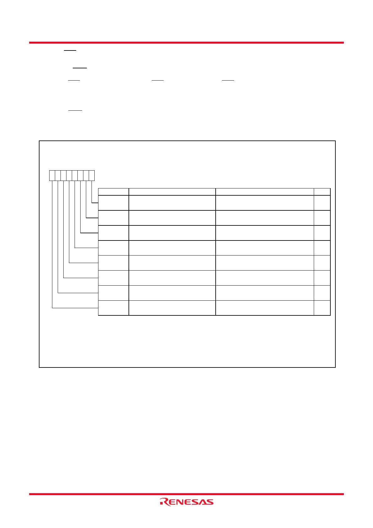
Figure 12.12 shows the INTEN Register. Figure 12.13 shows the INTF Register.
Figure 12.12 INTEN Register
External Input Enable Register
Symbol Address After Reset
INTEN
00F9h 00h
Bit Symbol Bit Name Function RW
INT0
____
input enable bit
INT0
____
input polarity select bit
(1,2)
INT1
____
input enable bit
INT1
____
input polarity select bit
(1,2)
INT2
____
input enable bit
INT2
____
input polarity select bit
(1,2)
INT3
____
input enable bit
INT3
____
input polarity select bit
(1,2)
NOTES:
1.
2.
0 : Disable
1 : Enable
RW
INT2EN
0 : Disable
1 : Enable
RW
INT2PL
0 : One edge
1 : Both edges
RW
When setting the INTiPL bit (i = 0 to 3) to 1 (both edges), set the POL bit in the INTiIC register to 0 (selects falling
edge).
The IR bit in the INTiIC register may be set to 1 (requests interrupt) w hen the INTiPL bit is rew ritten. Refer to
12.6.4
Changing Interrupt Sources
.
0 : Disable
1 : Enable
0 : One edge
1 : Both edges
0 : One edge
1 : Both edges
RW
INT0PL RW
INT1EN
0 : Disable
1 : Enable
RW
INT0EN
RW
INT1PL
0 : One edge
1 : Both edges
RW
INT3EN
INT3PL
b3 b2 b1 b0b7 b6 b5 b4
 Loading...