R8C/20 Group, R8C/21 Group 16. Clock Synchronous Serial Interface
Rev.2.00 Aug 27, 2008 Page 282 of 458
REJ09B0250-0200
16. Clock Synchronous Serial Interface
The clock synchronous serial interface is configured as follows.
Clock Synchronous Serial Interface
The clock synchronous serial interface uses the registers of addresses 00B8h to 00BFh. Registers, bits, symbols and
functions vary even in the same addresses depending on the modes. Refer to registers of each function for details.
Also, the differences between clock synchronous communication mode and clock synchronous serial mode are the
options of the transfer clock, clock output format and data output format.
16.1 Mode Selection
The clock synchronous serial interface contains 4 modes.
Table 16.1 lists the Mode Selections. Refer to 16.2 Clock Synchronous Serial I/O with Chip Select (SSU) or after
for details of each mode.
Clock synchronous serial I/O with chip select (SSU) Clock synchronous communication mode
4-wire bus communication mode
I
2
C bus interface I
2
C bus interface mode
Clock synchronous serial mode
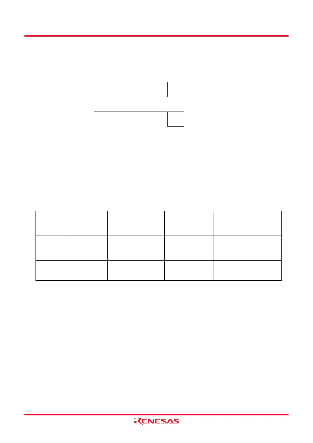
Table 16.1 Mode Selections
IICSEL Bit
in PMR
Register
Bit 7 in 00B8h
(ICE Bit in ICCR1
Register)
Bit 0 in 00BDh
(SSUMS Bit in SSMR2
Register, FS Bit in SAR
Register)
Function Mode
0 0 0 Clock synchronous
serial I/O with chip
select
Clock synchronous
communication mode
0 0 1 4-wire bus communication
mode
11 0
I
2
C bus interface I
2
C bus interface mode
1 1 1 Clock synchronous serial
mode
 Loading...