R8C/20 Group, R8C/21 Group 17. Hardware LIN
Rev.2.00 Aug 27, 2008 Page 352 of 458
REJ09B0250-0200
17.4.2 Slave Mode
Figure 17.7 shows a Typical Operation when Receiving a Header Field. Figure 17.8 through Figure 17.10 show
an Example of Header Field Reception Flowchart.
When receiving a header field, the hardware LIN operates as described below.
(1) Synch Break detection is enabled by writing 1 to the LSTART bit in the LINCR register of the hardware
LIN.
(2) When a low-level signal is input for a duration equal to or greater than the period set in timer RA, the
hardware LIN detects it as Synch Break. At this time, the SBDCT flag in the LINST register is set to 1.
Furthermore, if the SBIE bit in the LINCR register is set to 1, the hardware LIN generates a timer RA
interrupt. Then it goes to Synch Field measurement.
(3) The hardware LIN receives a Synch Field (55h). At this time, it measures the period of the start bit and
bits 0 to 6 by using timer RA. In this case, it is possible to select whether to input the Synch Field signal
to RxD0 of UART0 by setting the SBE bit in the LINCR register accordingly.
(4) The hardware LIN sets the SFDCT flag in the LINST register to 1 when it finished measuring the Synch
Field. Furthermore, if the SFIE bit in the LINCR register is set to 1, it generates a timer RA interrupt.
(5) After it finished measuring the Synch Field, the hardware LIN calculates a transfer rate from the count
value of timer RA and sets the result in UART0 and sets the TRAPRE and TRA registers of the timer
RA back again. Then it receives an ID field via UART0.
(6) The hardware LIN performs communication for a response field after it finished receiving the ID field.
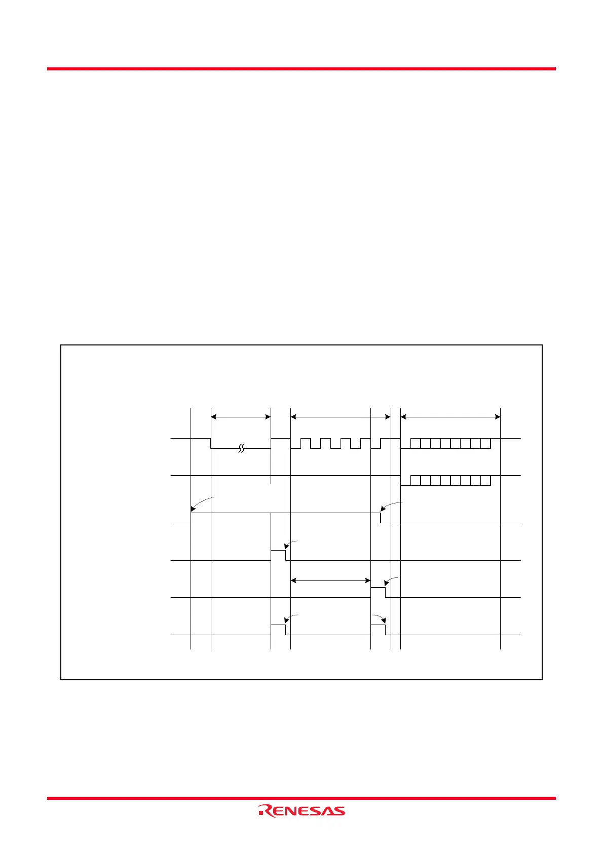
Figure 17.7 Typical Operation when Receiving a Header Field
RXD0 pin
Synch Break
1
0
RXD0 input for
UART0
1
0
RXDSF flag in the
LINCR register
1
0
Synch Field IDENTIFIER
(2) (3) (5) (6)
(4)(1)
SBDCT flag in the
LINST register
1
0
SFDCT flag in the
LINST register
1
0
IR bit in the TRAIC
register
1
0
Set by writing 1 to the
B0CLR bit in the LINST
register
Cleared to 0 when Synch
Field measurement
finishes
Measure this period
Set by writing 1 to
the B1CLR bit in
the LINST register
Cleared to 0 upon
acceptance of
interrupt request or
by a program
Set by writing 1 to
the LSTART bit in
the LINCR register
• When LINE bit = 1 (Causes LIN to start operating), MST bit = 0 (Slave mode), SBIE bit = 1
(Enables Synch Break detection interrupt), SFIE bit = 1 (Enables Synch Field measurement
completed interrupt)
 Loading...