R8C/20 Group, R8C/21 Group 14. Timers
Rev.2.00 Aug 27, 2008 Page 200 of 458
REJ09B0250-0200
14.3.7 PWM Mode
PWM mode is to output a PWM waveform. Up to 3 PWM waveforms with the same period can be output by 1
channel. Also, Up to 6 PWM waveforms with the same period can be output by synchronizing Channels 0 and
1. Since this mode functions by a combination of the TRDIOji (i = 0 or 1, j = B, C or D) pin and TRDGRji
register, any of PWM mode, other modes or functions can be selected every pin. (However, since the
TRDGRAi register is used when using any pin for PWM mode, the TRDGRAi register cannot be used for other
modes.)
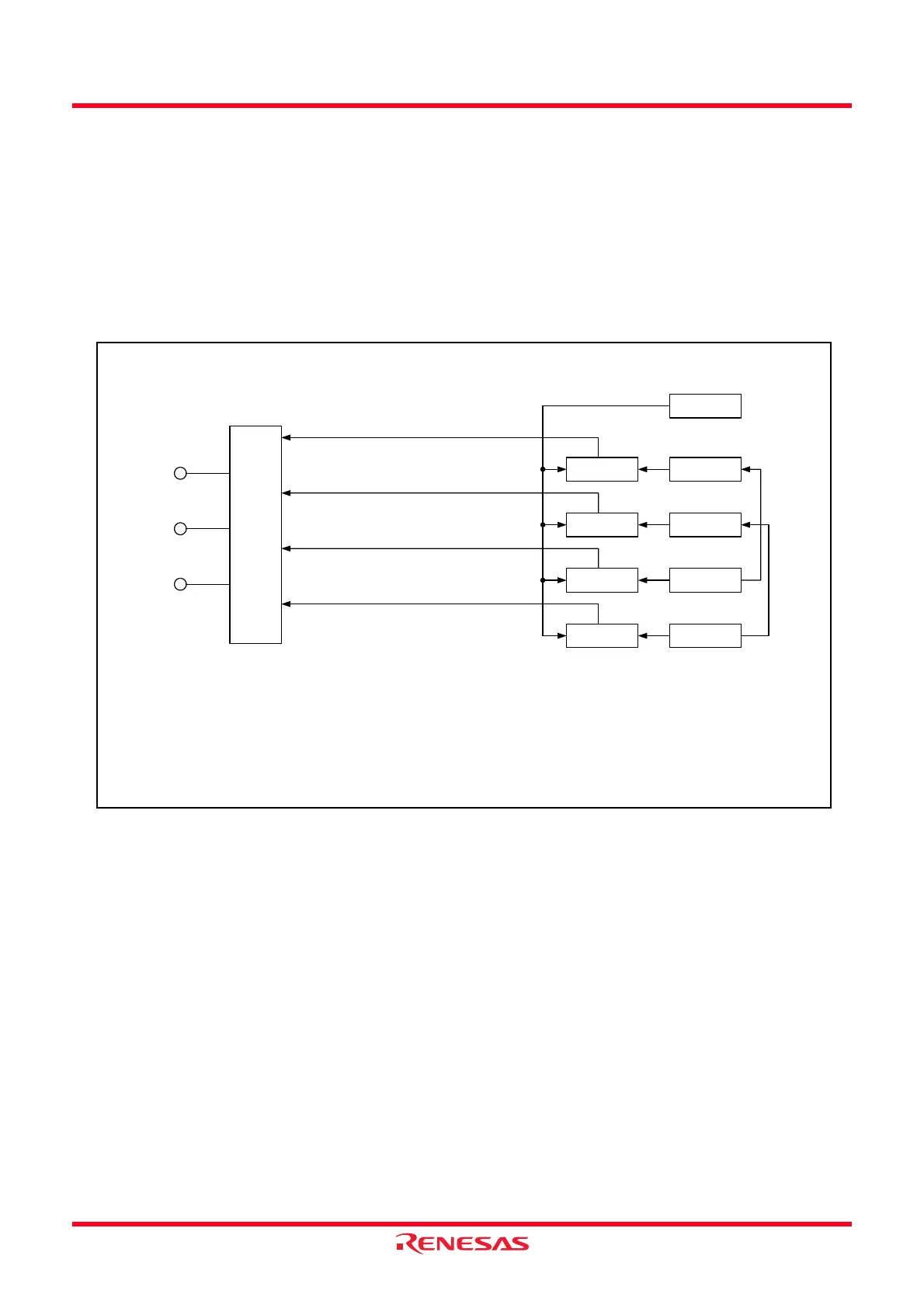
Figure 14.63 shows the Block Diagram of PWM Mode, Table 14.27 lists the PWM Mode Specifications.
Figures 14.64 to 14.73 show the Registers Associated with PWM Mode and Figures 14.74 to 14.75 show the
Operations of PWM Mode.
Figure 14.63 Block Diagram of PWM Mode
TRDIOBi
Output
control
TRDGRAi
TRDi
Compare match signal
TRDGRBi
TRDIOCi
TRDGRCi
TRDGRDi
TRDIODi
(Note 1)
(Note 2)
i = 0 or 1
NOTES:
1. When the BFCi bit in the TRDMR register is set to 1 (the TRDGRCi register is used as the
buffer register of the TRDGRAi register).
2. When the BFDi bit in the TRDMR register is set to 1 (the TRDGRDi register is used as the
buffer register of the TRDGRBi register).
Compare match signal
Compare match signal
Compare match signal
Comparator
Comparator
Comparator
Comparator
 Loading...