R8C/20 Group, R8C/21 Group 17. Hardware LIN
Rev.2.00 Aug 27, 2008 Page 357 of 458
REJ09B0250-0200
17.4.4 Hardware LIN End Processing
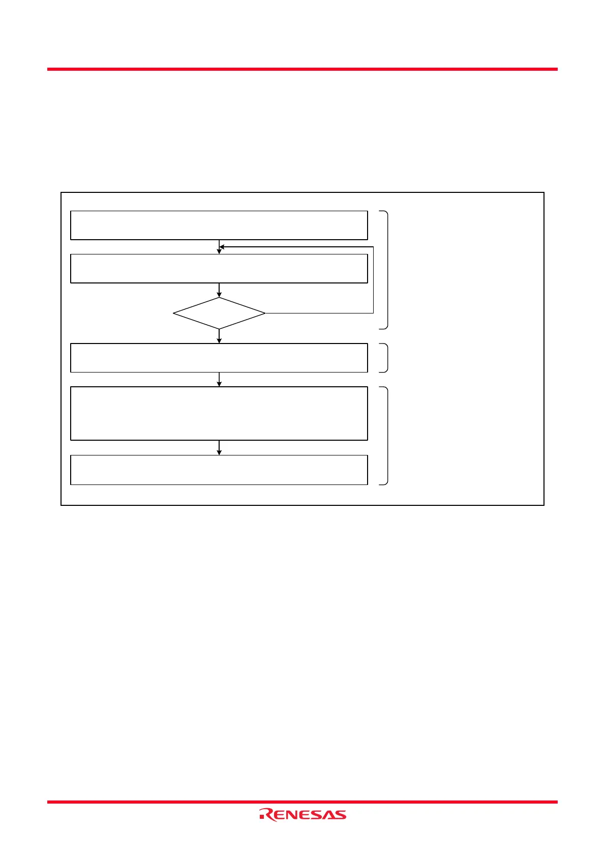
Figure 17.12 shows an Example of Hardware LIN Communication Completion Flowchart.
Use the following timing for hardware LIN end processing:
• If the hardware bus collision detection function is used
Perform hardware LIN end processing after checksum transmission completes.
• If the bus collision detection function is not used
Perform hardware LIN end processing after header field transmission and reception complete.
Figure 17.12 Example of Hardware LIN Communication Completion Flowchart
Hardware LIN Clear the status flags
(Bus collision detection, Synch Break detection, Synch
Field measurement)
Bits B2CLR, B1CLR, B0CLR in the LINST register
← 1
Timer RA Read the count status flag
TCSTF flag in TRACR register
UART0 Complete transmission via UART0
When the bus collision detection
function is not used, end
processing for the UART0
transmission is not required.
TCSTF = 0 ?
YES
NO
Set the timer to stop counting.
Zero to one cycle of the timer RA
count source is required after timer
RA starts counting before the
TCSTF flag is set to 1.
After clearing hardware LIN
status flag, stop the
hardware LIN operation.
Timer RA Set the timer to stop counting
TSTART bit in TRACR register
← 0
Hardware LIN Set the LIN operation to stop
LINE bit in the LINCR register
← 0
 Loading...