R8C/20 Group, R8C/21 Group 17. Hardware LIN
Rev.2.00 Aug 27, 2008 Page 345 of 458
REJ09B0250-0200
17. Hardware LIN
The hardware LIN performs LIN communication in cooperation with timer RA and UART0.
17.1 Features
The hardware LIN has the following features.
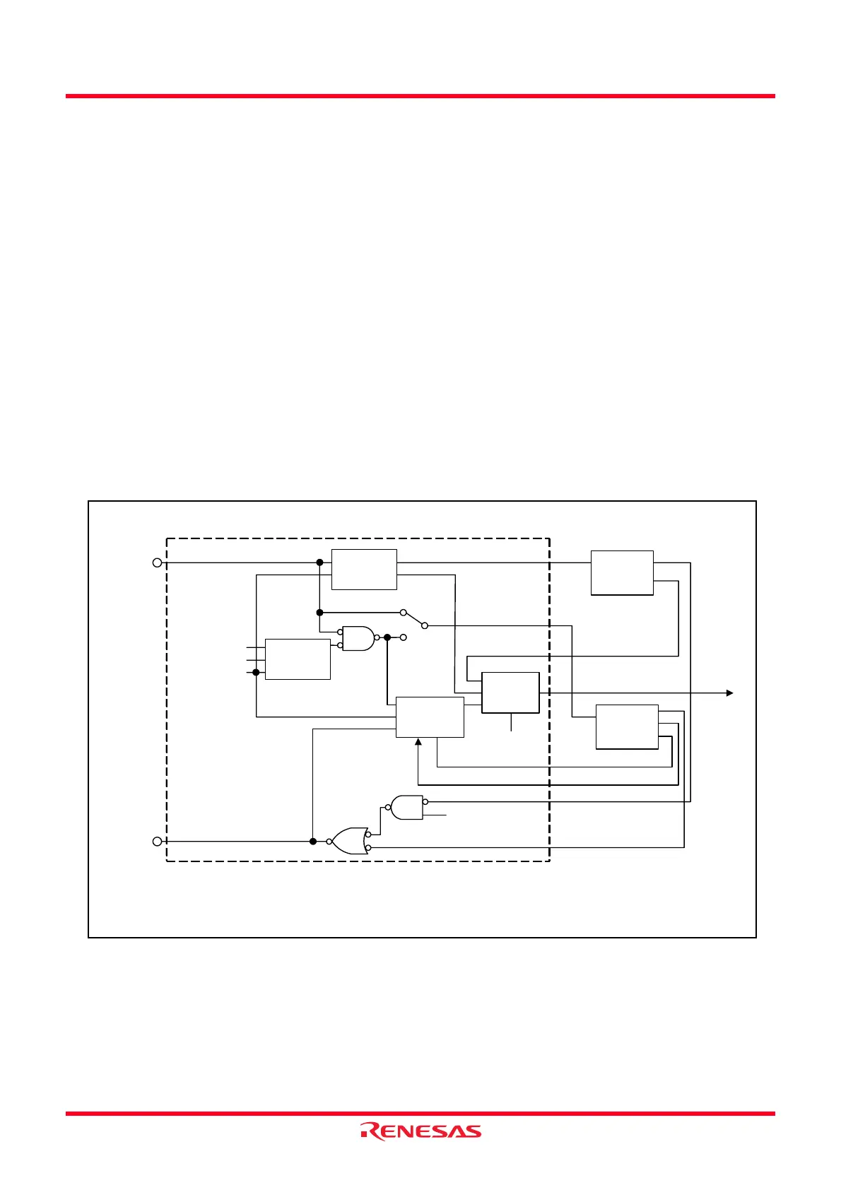
Figure 17.1 shows a Block Diagram of Hardware LIN.
[Master mode]
• Generates Synch Break
• Detects bus collision
[Slave mode]
• Detects Synch Break
• Measures Synch Field
• Controls Synch Break and Synch Field signal inputs to UART0
• Detects bus collision
NOTE:
1. The WakeUp function is detected by INT1.
Figure 17.1 Block Diagram of Hardware LIN
Timer RA
UART0
Interrupt
control
circuit
Bus collision
detection
circuit
Synch Field
control
circuit
RXD0 pin
TXD0 pin
LSTART bit
SBE bit
LINE bit
Timer RA
interrupt
TIOSEL = 0
Hardware LIN
TIOSEL = 1
RXD data
Timer RA
underflow signal
BCIE, SBIE,
and SFIE bits
UART0 transfer clock
UART0 TE bit
Timer RA output pulse
UART0 TXD data
MST bit
[Legend]
LINE, MST, SBE, LSTART, BCIE, SBIE, SFIE: LINCR register bits
TIOSEL: TRAIOC register bit
TE: U0C1 register bit
RXD0 input
control
circuit
 Loading...