R8C/20 Group, R8C/21 Group 12. Interrupts
Rev.2.00 Aug 27, 2008 Page 104 of 458
REJ09B0250-0200
12.3 Key Input Interrupt
A key input interrupt request is generated by one of the input edges of the K10 to K13 pins. The key input interrupt
can be used as a key-on wake-up function to exit wait or stop mode.
The KIiEN (i = 0 to 3) bit in the KIEN register can select whether the pins are used as KIi
input. The KIiPL bit in
the KIEN register can select the input polarity.
When inputting “L” to the KIi
pin which sets the KIiPL bit to 0 (falling edge), the input of the other K10 to K13
pins are not detected as interrupts. Also, when inputting “H” to the KIi pin which sets the KIiPL bit to 1 (rising
edge), the input of the other K10
to K13 pins are not detected as interrupts.
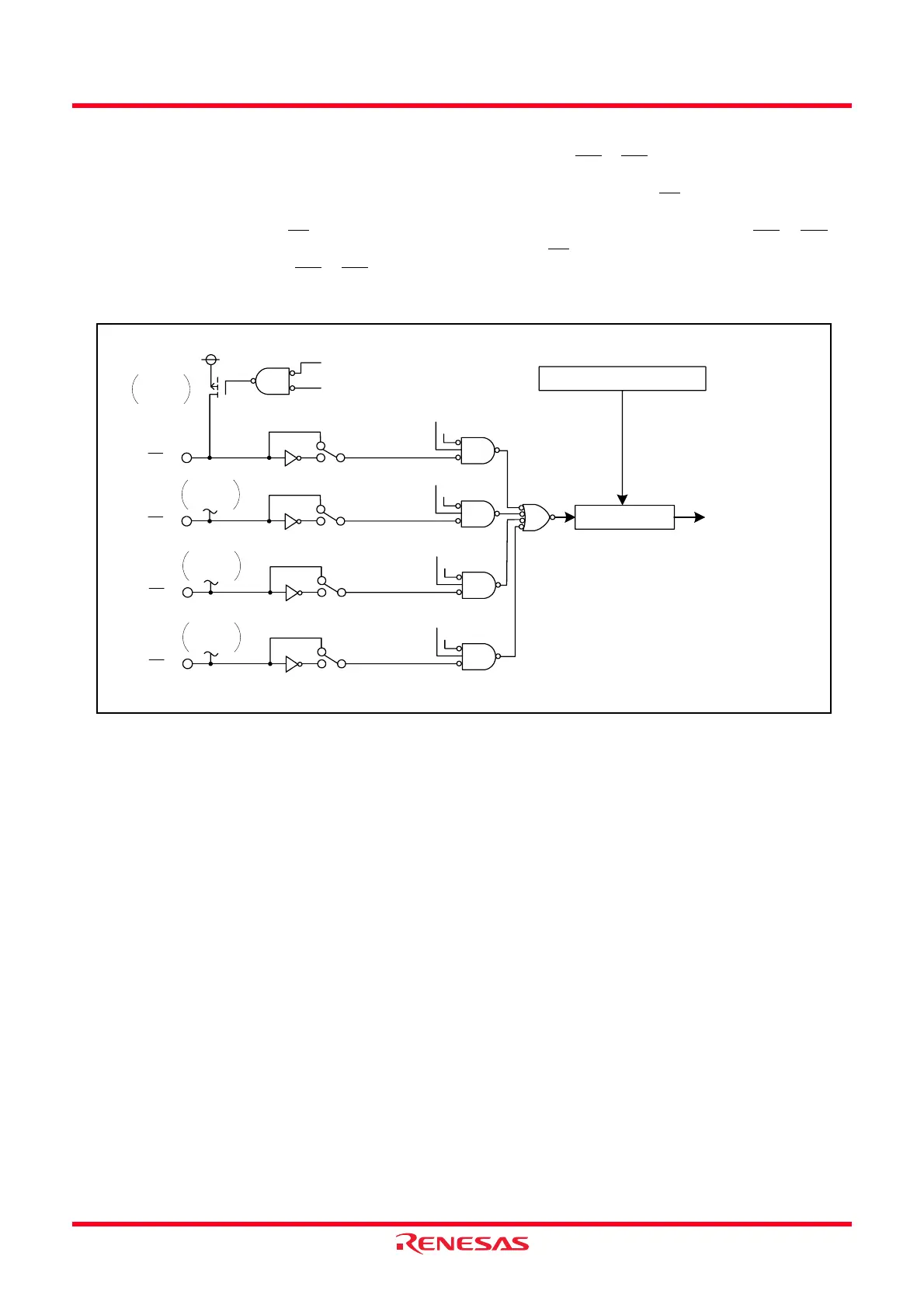
Figure 12.16 shows a Block Diagram of Key Input Interrupt.
Figure 12.16 Block Diagram of Key Input Interrupt
KI3
Pull-up
transistor
KI2
Pull-up
transistor
KI3PL = 0
KI3PL = 1
PD1_3 bit
KI3EN bit
PU02 bit in PUR0 register
PD1_3 bit in PD1 register
KUPIC register
Interrupt control
circuit
Key input interrupt
request
KI2PL = 0
KI2PL = 1
PD1_2 bit
KI2EN bit
KI1
Pull-up
transistor
KI1PL = 0
KI1PL = 1
PD1_1 bit
KI1EN bit
KI0
Pull-up
transistor
KI0PL = 0
KI0PL = 1
PD1_0 bit
KI0EN bit
KI0EN, KI1EN, KI2EN, KI3EN,
KI0PL, KI1PL, KI2PL, KI3PL: Bits in KIEN register
PD1_0, PD1_1, PD1_2, PD1_3: Bits in PD1 register
 Loading...