R8C/20 Group, R8C/21 Group 14. Timers
Rev.2.00 Aug 27, 2008 Page 184 of 458
REJ09B0250-0200
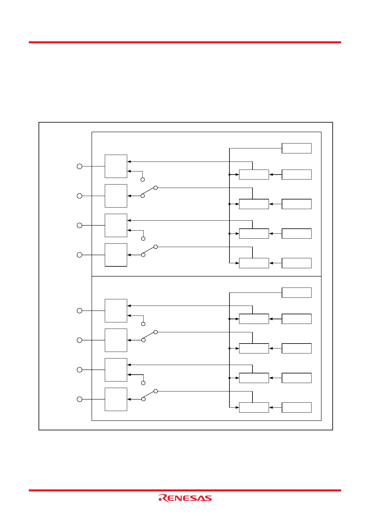
14.3.6 Output Compare Function
This function is to detect the match (compare match) of the content in the TRDGRji (j = either A, B, C and D)
register with the content in the TRDi (i = 0 or 1) register. When the content matches, any level is output from
the TRDIOji pin. Since this function is enabled with a combination of the TRDIOji pin and TRDGRji register,
any of the output compare function, other modes or functions can be selected every pin.
Figure 14.47 shows the Block Diagram of Output Compare Function, Table 14.25 lists the Output Compare
Function Specifications. Figures 14.48 to 14.59 list the Registers Associated with Output Compare Function
and Figure 14.60 shows the Operating Example of Output Compare Function.
Figure 14.47 Block Diagram of Output Compare Function
TRDIOA0
Output
control
Comparator TRDGRA0
TRD0
TRDIOC0
Output
control
Comparator TRDGRC0
Compare match signal
TRDIOB0
Output
control
Comparator TRDGRB0
TRDIOD0
Output
control
Comparator TRDGRD0
Channel 0
TRDIOA1
Output
control
Comparator TRDGRA1
TRD1
TRDIOC1
Output
control
Comparator TRDGRC1
TRDIOB1
Output
control
Comparator TRDGRB1
TRDIOD1
Output
control
Comparator TRDGRD1
Channel 1
Compare match signal
Compare match signal
Compare match signal
Compare match signal
Compare match signal
Compare match signal
Compare match signal
IOC3 = 0 in
TRDIORC0 register
IOC3 = 1
IOD3 = 0 in
TRDIORD0 register
IOD3 = 1
IOC3 = 0 in
TRDIORC1 register
IOC3 = 1
IOD3 = 0 in
TRDIORD1 register
IOD3 = 1
 Loading...