R8C/20 Group, R8C/21 Group 18. A/D Converter
Rev.2.00 Aug 27, 2008 Page 370 of 458
REJ09B0250-0200
18.3 Sample and Hold
When the SMP bit in the ADCON2 register is set to 1 (with sample and hold function), A/D conversion rate per pin
increases. The sample and hold function is available in all operating modes. Start the A/D conversion after
selecting whether the sample and hold circuit is to be used or not.
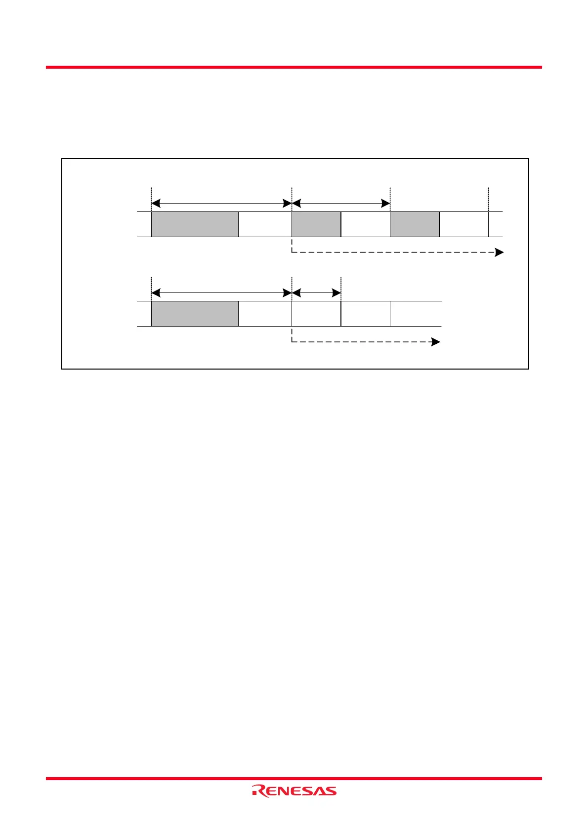
Figure 18.8 shows the Timing Diagram of A/D Conversion.
Figure 18.8 Timing Diagram of A/D Conversion
Sampling time
4ø AD cycle
Sample & hold
disabled
Conversion time at the 1st bit at the 2nd bit
Comparison
time
Sampling time
2.5ø AD cycle
Comparison
time
Sampling time
2.5ø AD cycle
Comparison
time
* Repeat until conversion ends
Sampling time
4ø AD cycle
Sample & hold
enabled
Conversion time at the 1st bit
at the 2nd bit
Comparison
time
Comparison
time
Comparison
time
* Repeat until conversion ends
Comparison
time
 Loading...