R8C/20 Group, R8C/21 Group 14. Timers
Rev.2.00 Aug 27, 2008 Page 129 of 458
REJ09B0250-0200
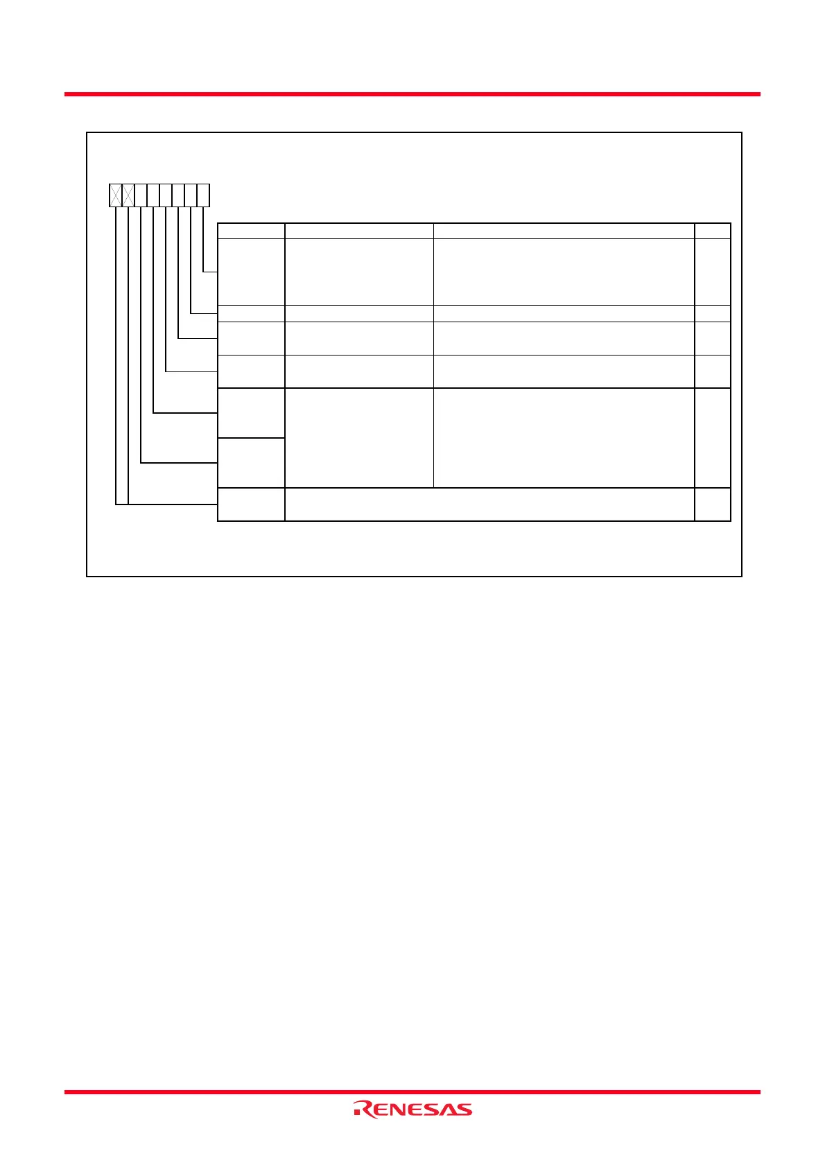
Figure 14.8 TRAIOC Register in Event Counter Mode
Timer RA I/O Control Register
Symbol Address After Reset
TRAIOC
0101h 00h
Bit Symbol Bit Name Function RW
INT1
____
/TRAIO select bit 0 : INT1
____
/TRAIO pin (P1_7)
1 : INT1
____
/TRAIO pin (P1_5)
NOTE:
1.
—
When the same value from the TRAIO pin is sampled three times continuously, the input is determined.
TRAIO output control bit Set to 0 in event counter mode
Nothing is assigned. If necessary, set to 0.
When read, the content is 0.
TRAO output enable bit
TRAIO input filter select
bits
(1)
b5 b4
0 0 : No filter
0 1 : Filter w ith f1 sampling
1 0 : Filter w ith f8 sampling
1 1 : Filter w ith f32 sampling
TIPF1
—
(b7-b6)
RW
TEDGSEL RW
TRAIO polarity sw itch bit
RW
TIPF0
RW
TOPCR RW
b3 b2b7 b6 b5 b4
0 : Port P3_0
1 : TRAO output
TIOSEL
b1 b0
0 : Starts counting at rising edge of the TRAIO
input or TRAIO starts output at “L”
1 : Starts counting at falling edge of the TRAIO
input or TRAIO starts output at “H”
0
TOENA
 Loading...