R8C/20 Group, R8C/21 Group 15. Serial Interface
Rev.2.00 Aug 27, 2008 Page 266 of 458
REJ09B0250-0200
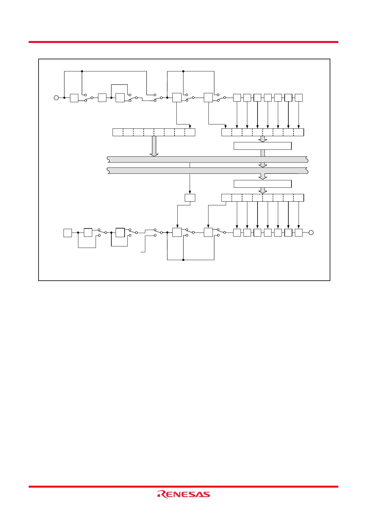
Figure 15.2 UARTi (i = 0 or 1) Transmit/Receive Unit
RXDi
1SP
2SP
SP
SP PAR
PRYE = 0
PAR
disabled
PAR
enabled
PRYE = 1
UART
UART (9 bits)
D7 D6 D5 D4 D3 D2 D1 D0
UARTi receive register
UiRB register
0000000D8
MSB/LSB conversion circuit
Data bus high-order bits
Data bus low-order bits
D7 D6 D5 D4 D3 D2 D1 D0
UiTB register
D8
TXDi
1SP
2SP
SP
SP PAR
UARTi transmit register
0
i = 0 or 1
SP: Stop bit
PAR: Parity bit
NOTE:
1. Clock synchronous type is provide in UART0 only.
UART (7 bits)
UART (8 bits)
Clock
synchronous
type
Clock
synchronous
type
UART (7 bits)
Clock
synchronous
type
UART (7 bits)
Clock
synchronous
type
UART (8 bits)
UART (9 bits)
UART (7 bits)
UART (8 bits)
Clock
synchronous
type
UART (9 bits)
UART
PRYE = 1
PAR
enabled
PAR
disabled
PRYE = 0
Clock
synchronous
type
MSB/LSB conversion circuit
UART (8 bits)
UART (9 bits)
 Loading...