R8C/20 Group, R8C/21 Group 18. A/D Converter
Rev.2.00 Aug 27, 2008 Page 365 of 458
REJ09B0250-0200
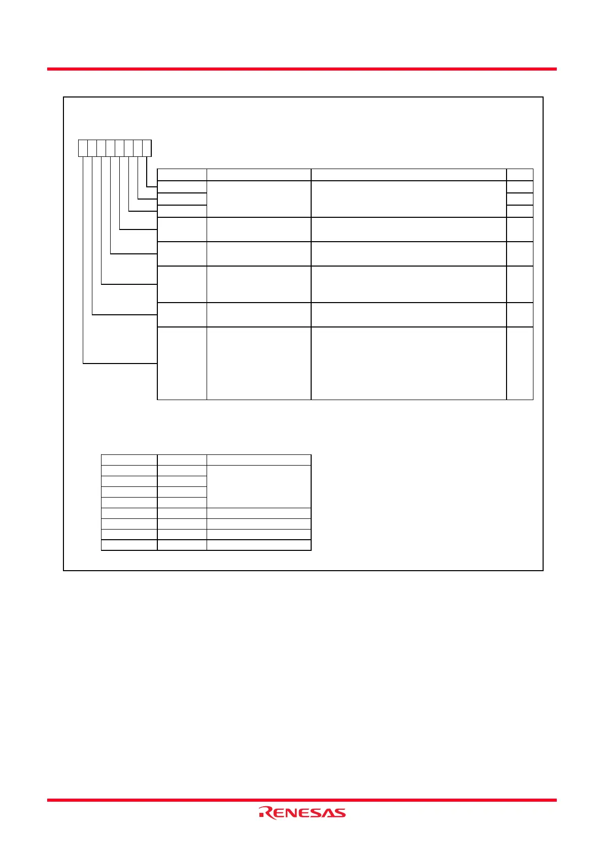
Figure 18.4 ADCON0 Register in One-Shot Mode
A/D Control Register 0
(1)
Symbol Address After Reset
ADCON0 00D6h 00h
Bit Symbol Bit Name Function RW
NOTES:
1.
2.
3.
4.
ADGSEL0 = 0
ADGSEL0 = 1
AN0
AN1
AN2
AN3
AN4 AN8
AN5 AN9
AN6 AN10
AN7 AN11
100b
101b
110b
111b
CH2 to CH0
000b Do not set
001b
010b
011b
b0
0
b3 b2 b1
MD
A/D operation mode select
bit
(2)
b7 b6 b5 b4
CH2 RW
Analog input pin select bit Refer to (4)
0 : One-shot mode
RW
RW
ADGSEL0 RW
A/D input group select bit
(4)
0 : Selects port P0 group (AN0 to AN7)
1 : Selects port P1 group (AN8 to AN11)
CH1 RW
CH0
ADCAP
A/D conversion automatic
start bit
0 : Starts in softw are trigger (ADST bit)
1 : Starts in timer RD
(complementary PWM mode)
RW
ADST
A/D conversion start flag 0 : Disables A/D conversion
1 : Starts A/D conversion
RW
Set øAD frequency to 10 MHz or below .
The analog input pin can be select according to a combination of the CH0 to CH2 bits and the ADGSEL0 bit.
CKS0
Frequency select bit 0 [When CKS1 in ADCON1 register = 0]
0 : Select f4
1 : Select f2
[When CKS1 in ADCON1 register = 1]
0 : Select f1
(3)
1 : Select fOCO-F
RW
If the ADCON0 register is rew ritten during A/D conversion, the conversion result is indeterminate.
When changing A/D operation mode, set the analog input pin again.
 Loading...