R8C/20 Group, R8C/21 Group 6. Voltage Detection Circuit
Rev.2.00 Aug 27, 2008 Page 31 of 458
REJ09B0250-0200
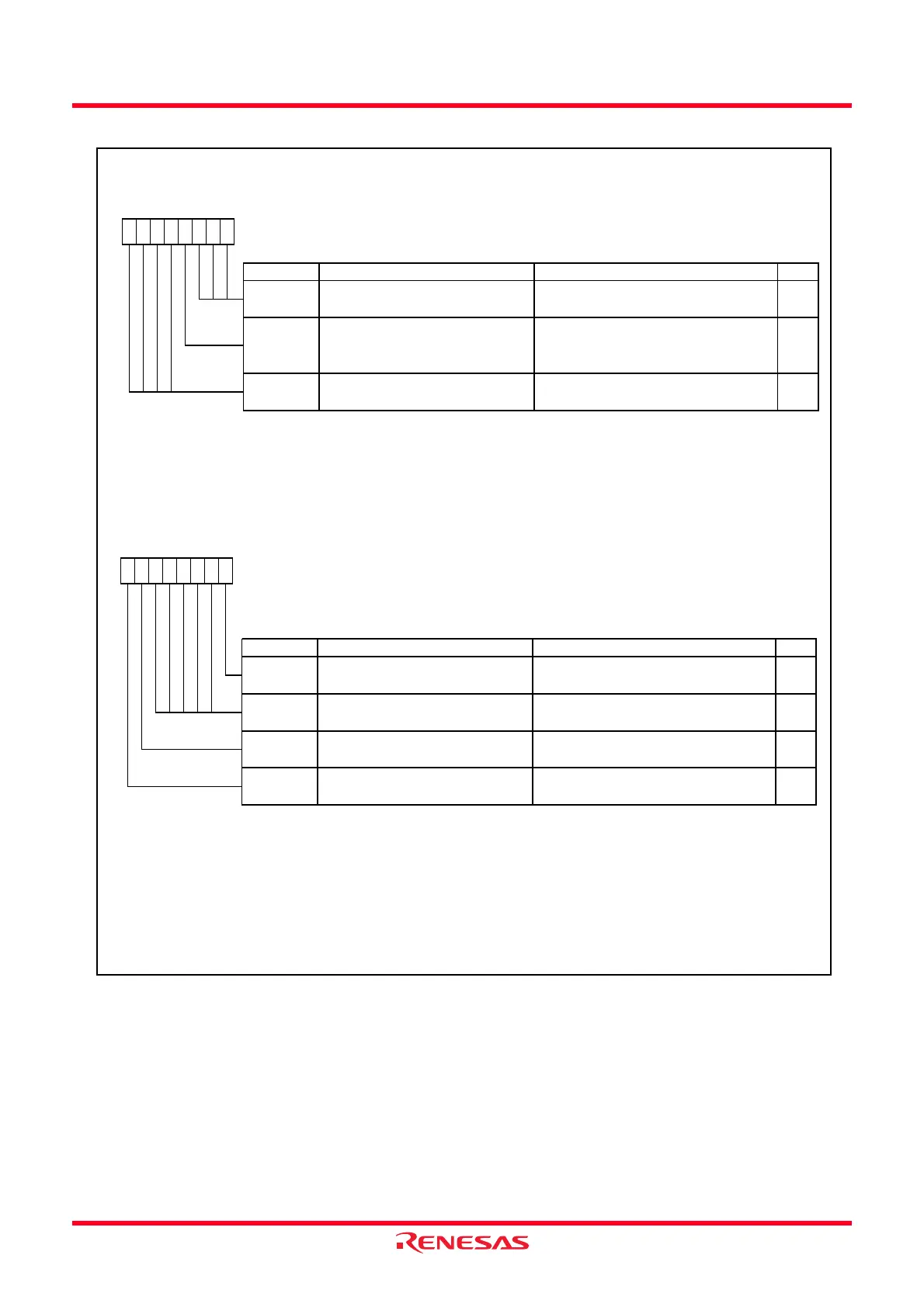
Figure 6.4 Registers VCA1 and VCA2
Voltage Detection Register 1
Symbol Address After Reset
(2)
VCA1
0031h 00001000b
Bit Symbol Bit Name Function RW
NOTES:
1.
2.
The VCA13 bit is enabled w hen the VCA27 bit in the VCA2 register is set to 1 (voltage detection 2 circuit enabled).
The VCA13 bit is set to 1 (VCC
≥
Vdet 2) w hen the VCA27 bit in the VCA2 register is set to 0 (voltage detection 2
circuit disabled
.
—
(b7-b4)
Reserved bits Set to 0
RW
Set to 0
0
b7 b6 b5 b4 b3 b2 b1 b0
0000
The softw are reset, w atchdog timer reset and voltage monitor 2 reset do not affect the VCA1 register.
VCA13
Voltage detection 2 signal monitor
flag
(1)
00
—
(b2-b0)
RW
0 : VCC < Vdet2
1 : VCC
≥
Vdet2 or voltage detection 2
circuit disabled
RO
Reserved bits
Voltage Detection Register 2
(1)
Symbol Address
VCA2 0032h
Bit Symbol Bit Name Function RW
NOTES:
1.
2.
3.
4.
5. Use the VCA20 bit only w hen entering to w ait mode. To set the VCA20 bit, follow the procedure show n in
Figure
10.10 Procedure for Enabling Reduced Internal Power Consumption Using VCA20 bit
.
VCA20
Internal power low consumption
enable bit
(5)
0 : Disables low consumption
1 : Enables low consumption
RW
When using the voltage monitor 2 interrupt/reset or the VCA13 bit in the VCA1 register, set the VCA27 bit to 1.
After the VCA27 bit is from 0 to 1, the voltage detection circuit elapses for td(E-A) before starting operation.
The VCA27 bit remains unchanged after softw are reset, w atchdog timer reset, and voltage monitor 2 reset.
Voltage detection 1 enable bit
(2)
0 : Voltage detection 1 circuit disabled
1 : Voltage detection 1 circuit enabled
RW
The LVD1ON bit in the OFS register is set to 1: 00h
Power-on reset, v oltage monitor 1 reset or the LVD1ON
bit in the OFS register is set to 0: 01000000b
After Reset
(4)
Set the PRC3 bit in the PRCR register to 1 (enables w riting) before w riting to the VCA2 register.
When using the voltage monitor 1 reset, set the VCA26 bit to 1.
After the VCA26 bit is set from 0 to 1, the voltage detection circuit elapses for td(E-A) before starting operation.
000
—
(b5-b1)
Reserved bits
VCA27
Voltage detection 2 enable bit
(3)
0 : Voltage detection 2 circuit disabled
1 : Voltage detection 2 circuit enabled
RW
b0
00
Set to 0
RW
VCA26
b7 b6 b5 b4 b3 b2 b1
 Loading...