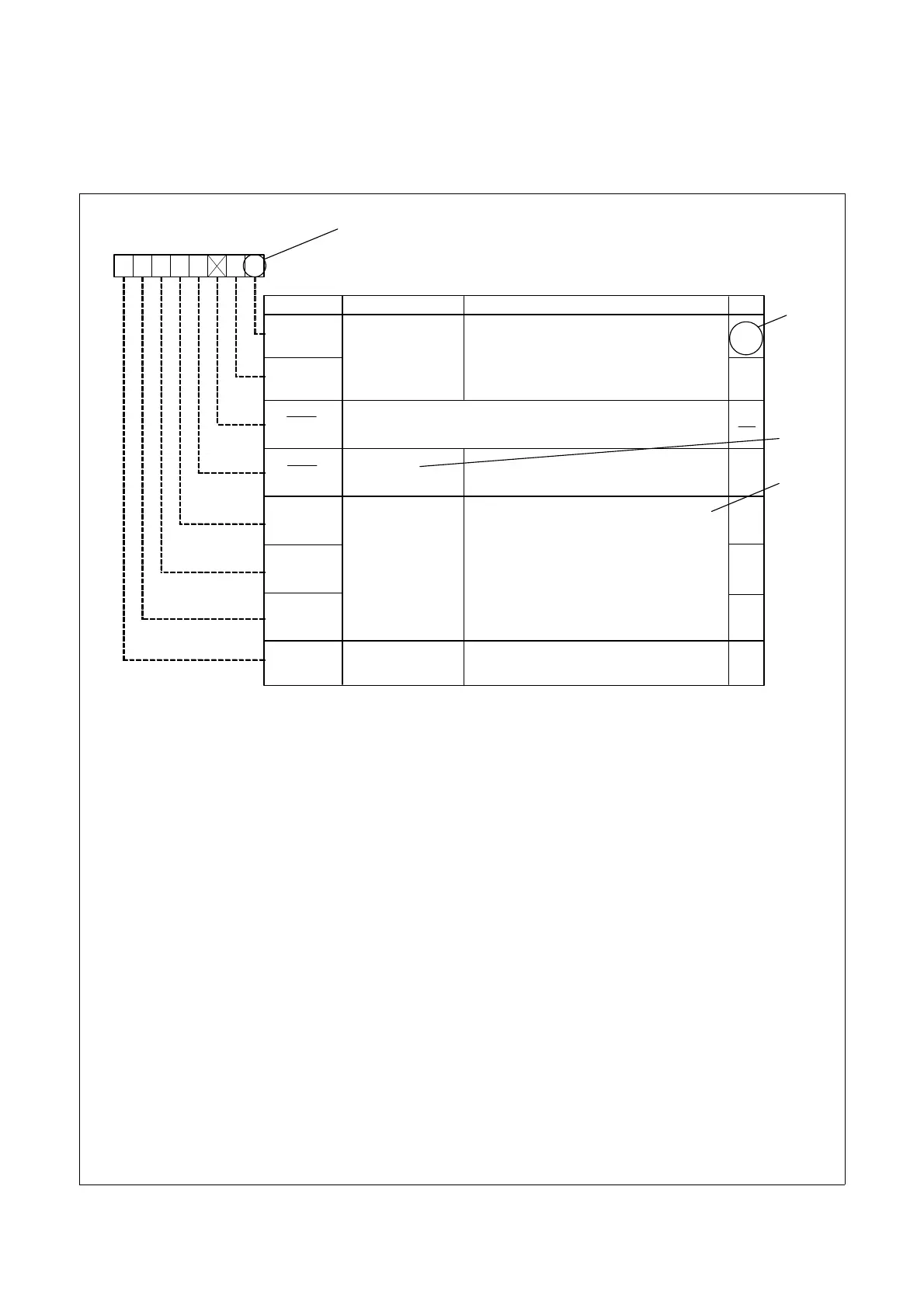
3. Register Notation
The symbols and terms used in register diagrams are described below.
*1
Blank: Set to 0 or 1 according to the application.
0: Set to 0.
1: Set to 1.
X: Nothing is assigned.
*2
RW: Read and write.
RO: Read only.
WO: Write only.
−: Nothing is assigned.
*3
• Reserved bit
Reserved bit. Set to specified value.
*4
• Nothing is assigned
Nothing is assigned to the bit. As the bit may be used for future functions, if necessary, set to 0.
• Do not set to a value
Operation is not guaranteed when a value is set.
• Function varies according to the operating mode.
The function of the bit varies with the peripheral function mode. Refer to the register diagram for information
on the individual modes.
XXX Register
Symbol Address After Reset
XXX XXX 00h
Bit NameBit Symbol
RW
b7 b6 b5 b4 b3 b2 b1 b0
XXX bits
1 0: XXX
0 1: XXX
1 0: Do not set.
1 1: XXX
b1 b0
XXX1
XXX0
XXX4
Reserved bits
XXX5
XXX7
XXX6
Function
Nothing is assigned. If necessary, set to 0.
When read, the content is undefined.
XXX bit
Function varies according to the operating
mode.
Set to 0.
0
(b3)
(b2)
RW
RW
RW
RW
WO
RW
RO
XXX bits
0: XXX
1: XXX
*1
*2
*3
*4
 Loading...