R8C/20 Group, R8C/21 Group 7. Programmable I/O Ports
Rev.2.00 Aug 27, 2008 Page 49 of 458
REJ09B0250-0200
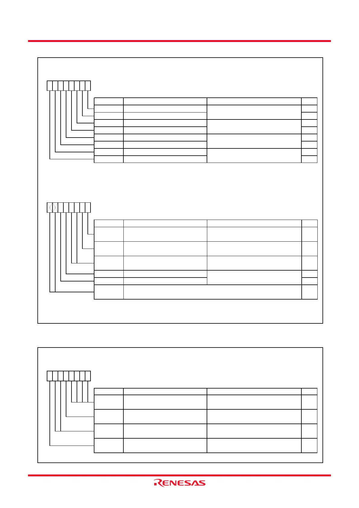
Figure 7.11 Registers PUR0 and PUR1
Figure 7.12 PMR Register
Pull-Up Control Register 0
Symbol Address After Reset
PUR0
00FCh 00h
Bit Symbol Bit Name Function RW
NOTE:
1. When this bit is set to 1 (pulled up), the pin w hose direct bit is set to 0 (input mode) is pulled up.
PU07
PU05
RWP3_4 to P3_5, and P3_7 pull-up
(1)
P2_4 to P2_7 pull-up
(1)
RW
PU06
b3 b2 b1 b0
PU00
b7 b6 b5 b4
RW
P0_4 to P0_7 pull-up
(1)
P0_0 to P0_3 pull-up
(1)
P1_0 to P1_3 pull-up
(1)
PU01
PU02
RW
RW
RW
0 : Not pulled up
1 : Pulled up
0 : Not pulled up
1 : Pulled up
0 : Not pulled up
1 : Pulled up
0 : Not pulled up
1 : Pulled up
PU03 P1_4 to P1_7 pull-up
(1)
P3_0, P3_1, and P3_3 pull-up
(1)
RW
P2_0 to P2_3 pull-up
(1)
PU04 RW
Pull-Up Control Register 1
Symbol Address After Reset
PUR1
00FDh XX00XX00b
Bit Symbol Bit Name Function RW
NOTE:
1.
RW
PU14 P6_0 to P6_3 pull-up
(1)
RW0 : Not pulled up
1 : Pulled up
b0
—
When this bit is set to 1 (pulled up) and the pin w hose direct bit is set to 0 (input mode), the pin is pulled up.
b3 b2
0
b1
0
b7 b6 b5 b4
—
(b7-b6)
Nothing is assigned. If necessary, set to 0.
When read, the content is 0.
PU10
P4_3 pull-up
(1)
0 : Not pulled up
1 : Pulled up
Reserved bits
RW
PU15 P6_4 to P6_7 pull-up
(1)
RW
PU11
P4_4 and P4_5 pull-up
(1)
0 : Not pulled up
1 : Pulled up
RW
—
(b3-b2)
Set to 0
Port Mode Registe
Symbol Address After Reset
PMR
00F8h 00h
Bit Symbol Bit Name Function RW
IICSEL RW
0 : SSU function selects
1 : I
2
C bus function selects
Set to 0
0 : I/O port P6_6, P6_7
1 : TXD1, RXD1
Set to 0
—
Reserved bits
SSU/I
2
C bus sw itch bit
RW
b0
0
—
Reserved bits
U1PINSEL
Port TXD1/RXD1 switch bit
—
(b3-b0)
—
(b6-b5)
b3 b2
0
b1
00
b7 b6 b5 b4
00
 Loading...