RL78/G13 CHAPTER 4 PORT FUNCTIONS
R01UH0146EJ0100 Rev.1.00 232
Sep 22, 2011
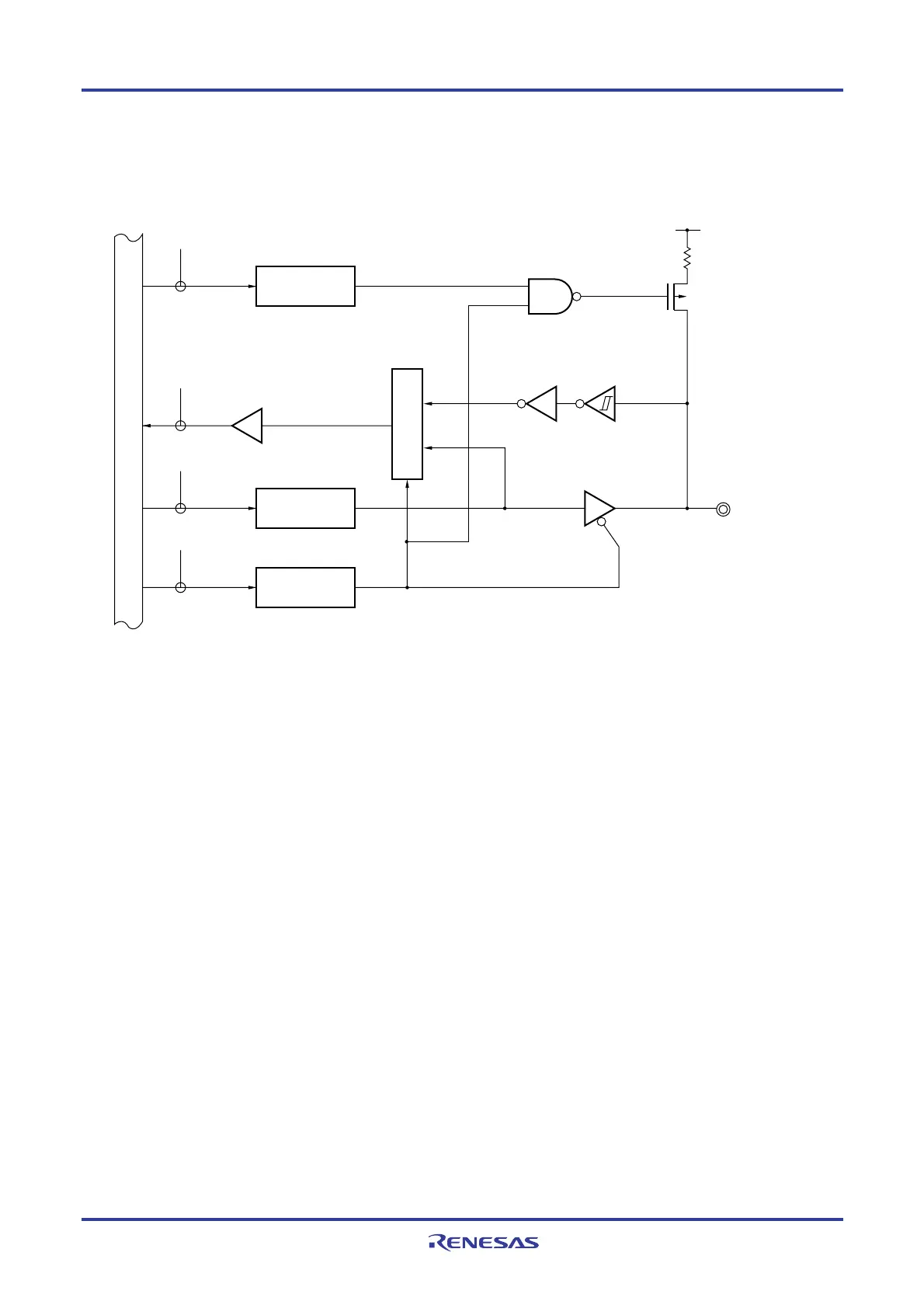
For example, 4-49 and 4-50 show block diagrams of port 11 for 128-pin products when PIOR = 00H.
Figure 4-49. Block Diagram of P110 to P114
P110 to P114
WR
PU
RD
WR
PORT
WR
PM
EV
DD
P-ch
PU11
PM11
P11
PM110 to PM114
PU110 to PU114
Output latch
(P110 to P114)
Selector
Internal bus
P11: Port register 11
PU11: Pull-up resistor option register 11
PM11: Port mode register 11
RD: Read signal
WR××: Write signal
<R>

 Loading...


