RL78/G13 CHAPTER 12 SERIAL ARRAY UNIT
R01UH0146EJ0100 Rev.1.00 668
Sep 22, 2011
12.7 LIN Communication Operation
12.7.1 LIN transmission
Of UART transmission, UART2 of the 30, 32, 36, 40, 44, 48, 52, 64, 80, 100, and 128-pin products support LIN
communication.
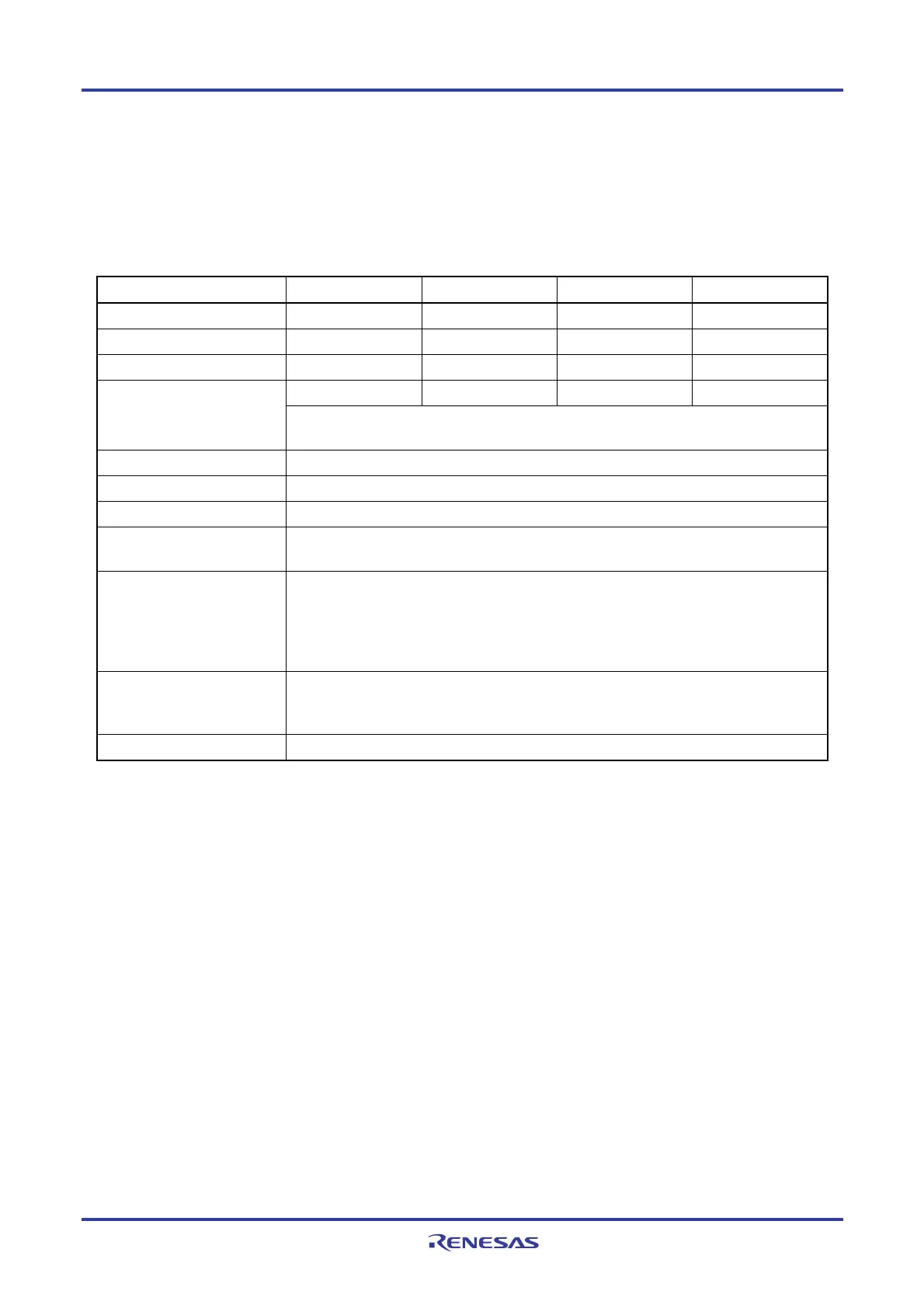
For LIN transmission, channel 0 of unit 1 is used.
UART UART0 UART1 UART2 UART3
Support of LIN communication Not supported Not supported Supported Not supported
Target channel
− −
Channel 0 of SAU1
−
Pins used
− −
TxD2
−
− −
INTST2
−
Interrupt
Transfer end interrupt (in single-transfer mode) or buffer empty interrupt (in continuous transfer
mode) can be selected.
Error detection flag None
Transfer data length 8 bits
Transfer rate Max. fMCK/6 [bps] (SDR10 [15:9] = 3 or more), Min. fCLK/(2 × 2
15
× 128) [bps]
Note
Data phase Forward output (default: high level)
Reverse output (default: low level)
Parity bit The following selectable
• No parity bit
• Appending 0 parity
• Appending even parity
• Appending odd parity
Stop bit The following selectable
• Appending 1 bit
• Appending 2 bits
Data direction MSB or LSB first
Note Use this operation within a range that satisfies the conditions above and the AC characteristics in the electrical
specifications (see CHAPTER 29 ELECTRICAL SPECIFICATIONS).
Remark f
MCK: Operation clock frequency of target channel
fCLK: System clock frequency

 Loading...


