RL78/G13 CHAPTER 17 KEY INTERRUPT FUNCTION
R01UH0146EJ0100 Rev.1.00 850
Sep 22, 2011
CHAPTER 17 KEY INTERRUPT FUNCTION
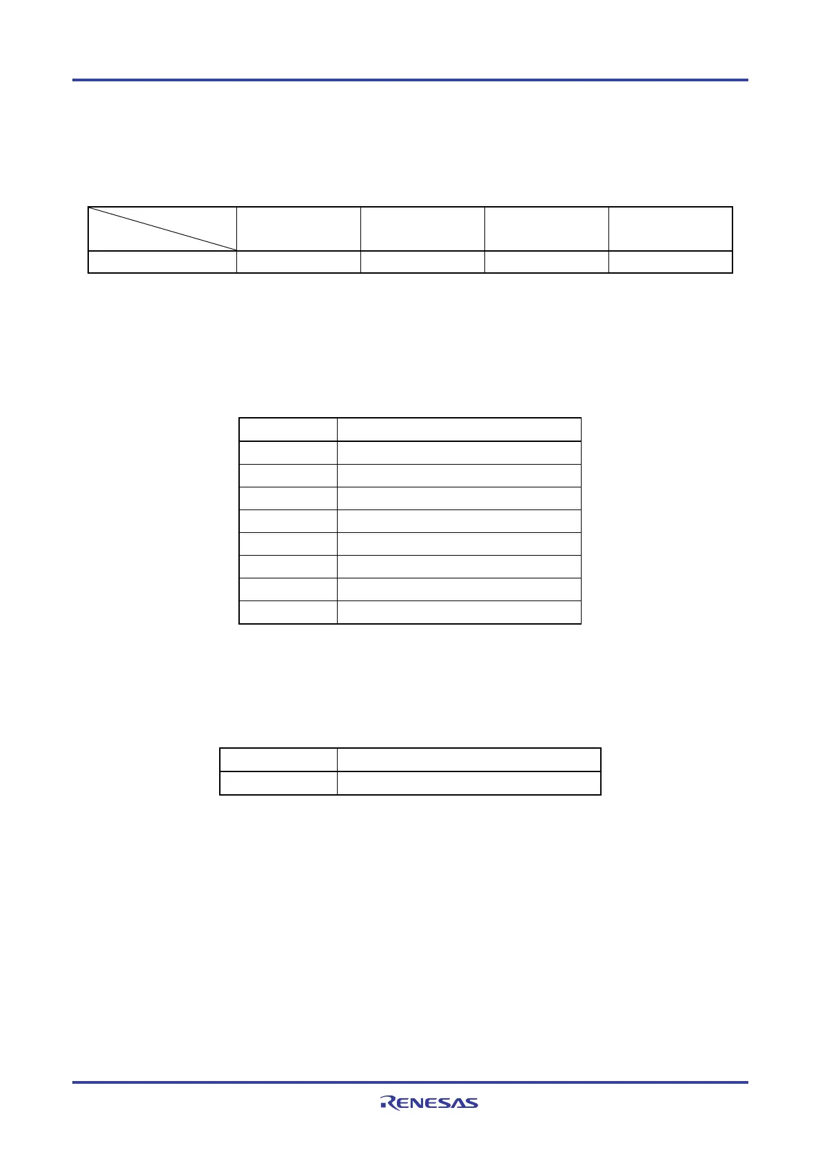
The number of key interrupt input channels differs, depending on the product.
20, 24, 25, 30, 32, 36-
pin
40, 44-pin 48-pin
52, 64, 80, 100, 128-
pin
Key interrupt input channels
−
4 ch 6 ch 8 ch
17.1 Functions of Key Interrupt
A key interrupt (INTKR) can be generated by setting the key return mode register (KRM) and inputting a falling edge to
the key interrupt input pins (KR0 to KR7).
Table 17-1. Assignment of Key Interrupt Detection Pins
Flag Description
KRM0 Controls KR0 signal in 1-bit units.
KRM1 Controls KR1 signal in 1-bit units.
KRM2 Controls KR2 signal in 1-bit units.
KRM3 Controls KR3 signal in 1-bit units.
KRM4 Controls KR4 signal in 1-bit units.
KRM5 Controls KR5 signal in 1-bit units.
KRM6 Controls KR6 signal in 1-bit units.
KRM7 Controls KR7 signal in 1-bit units.
17.2 Configuration of Key Interrupt
The key interrupt includes the following hardware.
Table 17-2. Configuration of Key Interrupt
Item Configuration
Control register Key return mode register (KRM)
Remark KR0 to KR3: 40, 44-pin products
KR0 to KR5: 48-pin products
KR0 to KR7: 52, 64, 80, 100, 128-pin products

 Loading...


