RL78/G13 CHAPTER 21 VOLTAGE DETECTOR
R01UH0146EJ0100 Rev.1.00 888
Sep 22, 2011
21.2 Configuration of Voltage Detector
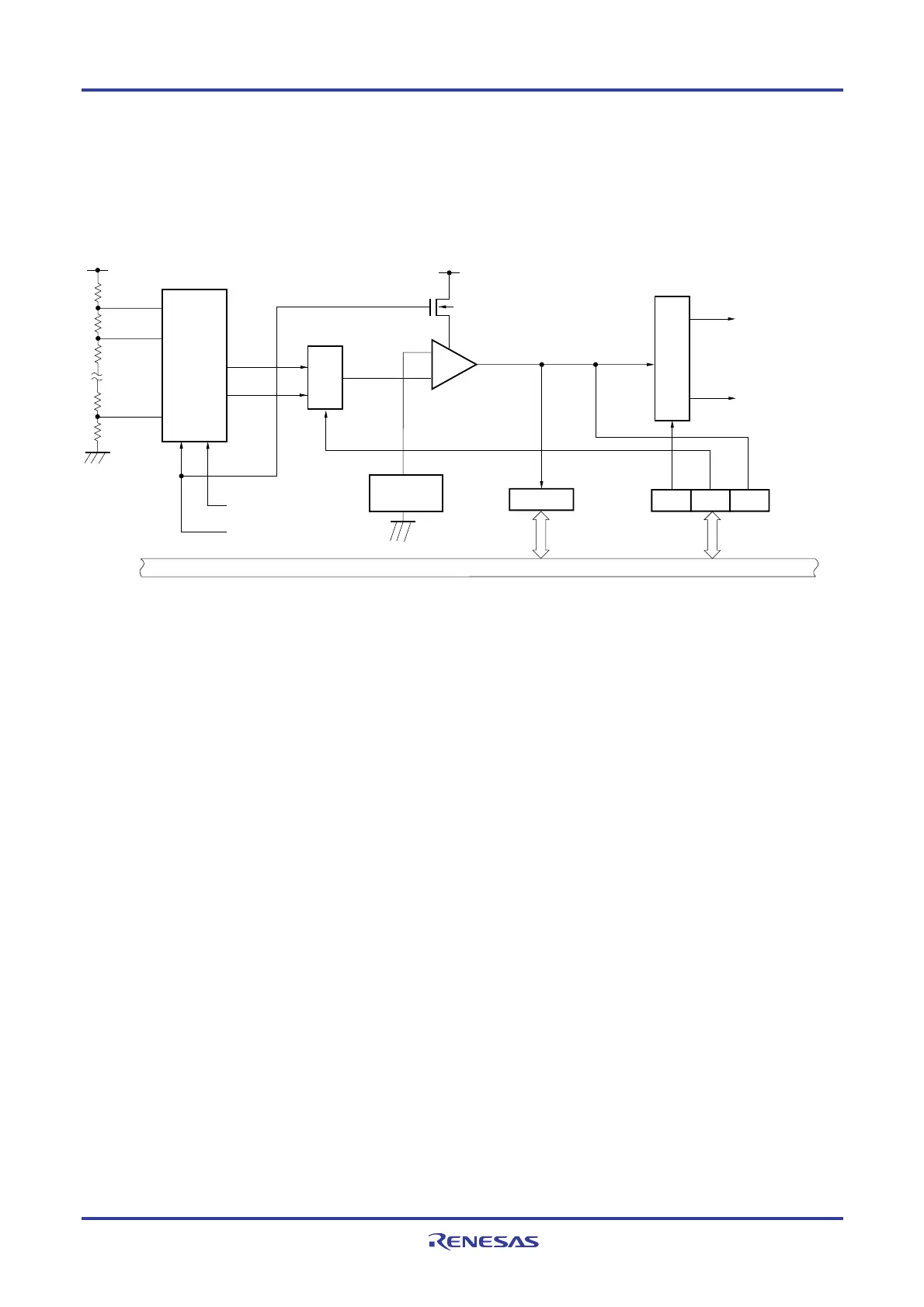
The block diagram of the voltage detector is shown in Figure 21-1.
Figure 21-1. Block Diagram of Voltage Detector
Voltage detection
level register (LVIS)
Voltage detection
register (LVIM)
VDD
LVIOMSK
INTLVI
Internal reset signal
VDD
LVILV
LVIMD
LVIF
VLVIH
VLVIL
Voltage detection
level selector
Reference
voltage
source
Selector
Internal bus
Controller
Option byte (000C1H)
VPOC2 to VPOC0
−
+
N-ch
Option byte (000C1H)
LVIS1, LVIS0
21.3 Registers Controlling Voltage Detector
The voltage detector is controlled by the following registers.
• Voltage detection register (LVIM)
• Voltage detection level register (LVIS)

 Loading...


