RL78/G13 CHAPTER 11 A/D CONVERTER
R01UH0146EJ0100 Rev.1.00 525
Sep 22, 2011
11.8 SNOOZE Mode Function
In the SNOOZE mode, A/D conversion is triggered by inputting a hardware trigger in the STOP mode. Normally, A/D
conversion is stopped while in the STOP mode, but, by using the SNOOZE mode, A/D conversion can be performed
without operating the CPU by inputting a hardware trigger. This is effective for reducing the operation current.
In the SNOOZE mode, only the following two conversion modes can be used:
• Hardware trigger wait mode (select mode, one-shot conversion mode)
• Hardware trigger wait mode (scan mode, one-shot conversion mode)
Note that the SNOOZE mode can only be specified when the high-speed on-chip oscillator clock is selected for f
CLK.
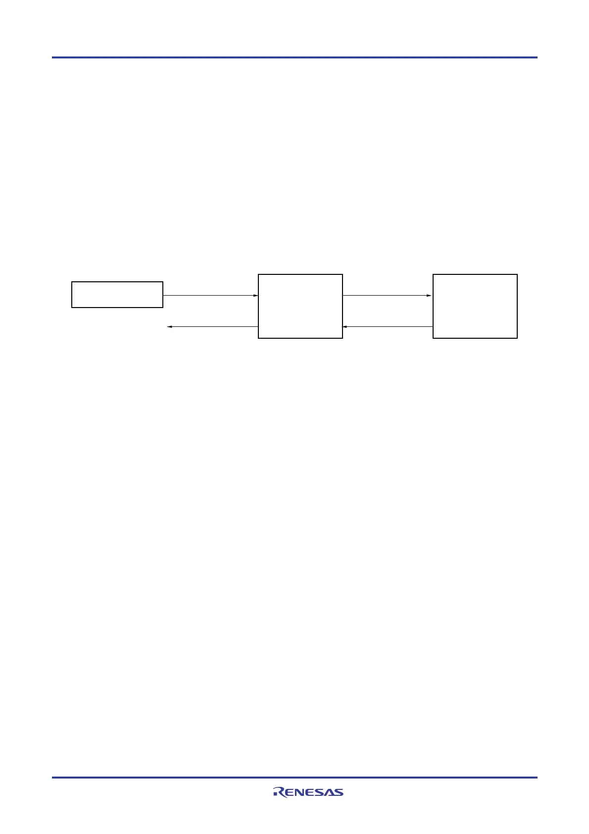
Figure 11-37. Block Diagram When Using SNOOZE Mode Function
Real-time clock (RTC),
Interval timer
Hardware trigger
input
Clock request signal
(internal signal)
High-speed on-chip
oscillator clock
A/D converter
Clock generator
A/D conversion end
interrupt request
signal
Note 1
(INTAD)
When using the SNOOZE mode function, the initial setting of each register is specified before switching to the STOP
mode. (For details about these settings, see 11.7.3 Setting up hardware trigger wait mode
Note 2
.) At this time, bit 2
(AWC) of A/D converter mode register 2 (ADM2) is set to 1. After the initial settings are specified, bit 0 (ADCE) of A/D
converter mode register 0 (ADM0) is set to 1.
If a hardware trigger is input after switching to the STOP mode, the high-speed on-chip oscillator clock is supplied to
the A/D converter. After supplying this clock, the system automatically counts up to the stabilization wait time, and then
A/D conversion starts.
The SNOOZE mode operation after A/D conversion ends differs depending on whether an interrupt signal is
generated
Note 1
.
Notes 1. Depending on the setting of the A/D conversion result comparison function (ADRCK bit, ADUL/ADLL
register), there is a possibility of no interrupt signal being generated.
2. Be sure to set the ADM1 register to E2H or E3H.
Remark The hardware trigger is INTRTC or INTIT.
Specify the hardware trigger by using the A/D Converter Mode Register 1 (ADM1).

 Loading...


