RL78/G13 CHAPTER 12 SERIAL ARRAY UNIT
R01UH0146EJ0100 Rev.1.00 651
Sep 22, 2011
12.6.2 UART reception
UART reception is an operation wherein the RL78/G13 asynchronously receives data from another device (start-stop
synchronization).
For UART reception, the odd-number channel of the two channels used for UART is used. The SMR register of both the
odd- and even-numbered channels must be set.
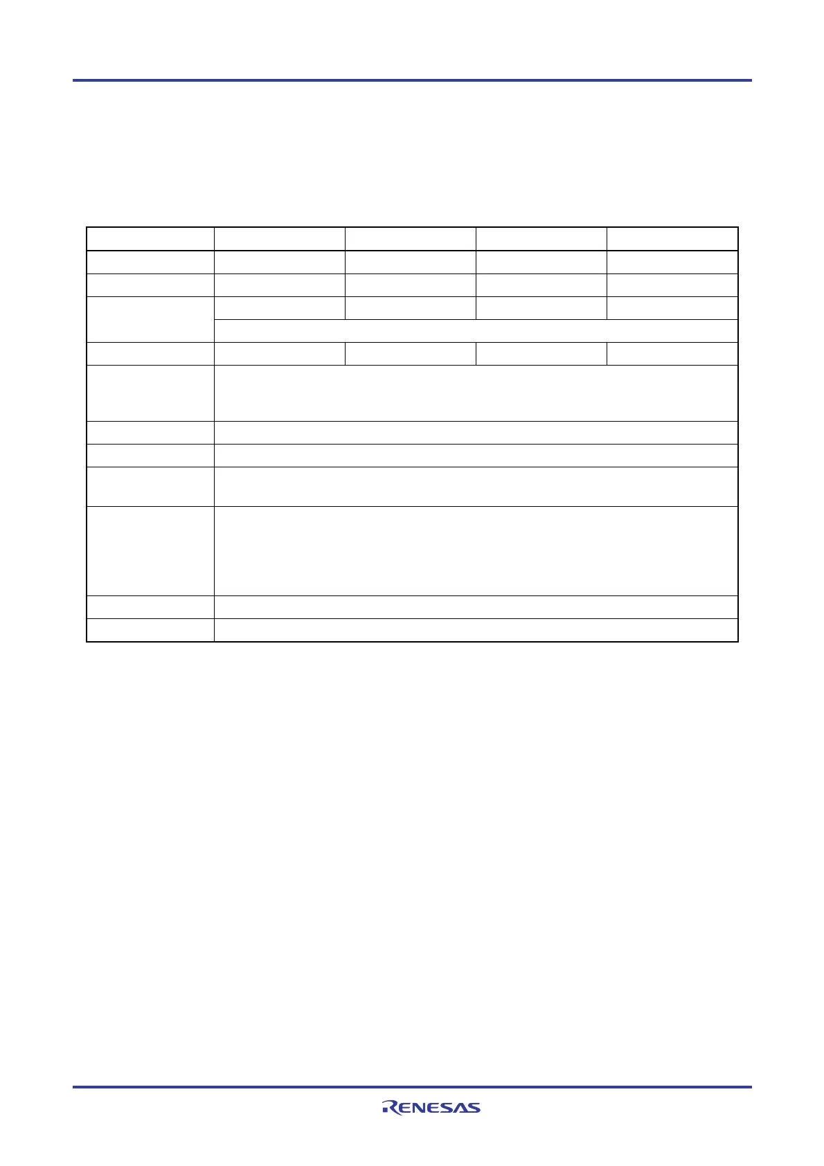
UART UART0 UART1 UART2 UART3
Target channel Channel 1 of SAU0 Channel 3 of SAU0 Channel 1 of SAU1 Channel 3 of SAU1
Pins used RxD0 RxD1 RxD2 RxD3
INTSR0 INTSR1 INTSR2 INTSR3 Interrupt
Transfer end interrupt only (Setting the buffer empty interrupt is prohibited.)
Error interrupt INTSRE0 INTSRE1 INTSRE2 INTSRE3
Error detection flag • Framing error detection flag (FEFmn)
• Parity error detection flag (PEFmn)
• Overrun error detection flag (OVFmn)
Transfer data length 7, 8 or 9 bits
Note 1
Transfer rate Max. fMCK/6 [bps] (SDRmn [15:9] = 3 or more), Min. fCLK/(2 × 2
15
× 128) [bps]
Note 2
Data phase Forward output (default: high level)
Reverse output (default: low level)
Parity bit The following selectable
• No parity bit (no parity check)
• Appending 0 parity (no parity check)
• Appending even parity
• Appending odd parity
Stop bit Appending 1 bit
Data direction MSB or LSB first
Notes 1. Only following UARTs can be specified for the 8-bit data length.
• 24 to 64-pin products: UART0 only
• 80, 100, 128-pin products: UART0 and UART2 only
2. Use this operation within a range that satisfies the conditions above and the AC characteristics in the
electrical specifications (see CHAPTER 29 ELECTRICAL SPECIFICATIONS).
Remarks 1. f
MCK: Operation clock frequency of target channel
f
CLK: System clock frequency
2. m: Unit number (m = 0, 1), n: Channel number (n = 1, 3), mn = 01, 03, 11, 13
<R>
 Loading...


