RL78/G13 CHAPTER 9 CLOCK OUTPUT/BUZZER OUTPUT CONTROLLER
R01UH0146EJ0100 Rev.1.00 467
Sep 22, 2011
9.4 Operations of Clock Output/Buzzer Output Controller
One pin can be used to output a clock or buzzer sound.
The PCLBUZ0 pin outputs a clock/buzzer selected by the clock output select register 0 (CKS0).
The PCLBUZ1 pin outputs a clock/buzzer selected by the clock output select register 1 (CKS1).
9.4.1 Operation as output pin
The PCLBUZn pin is output as the following procedure.
<1> Select the output frequency with bits 0 to 3 (CCSn0 to CCSn2, CSELn) of the clock output select register (CKSn)
of the PCLBUZn pin (output in disabled status).
<2> Set bit 7 (PCLOEn) of the CKSn register to 1 to enable clock/buzzer output.
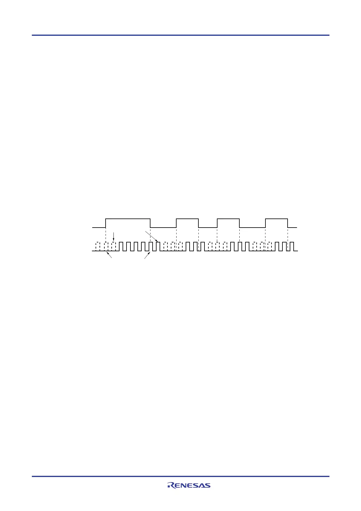
Remarks 1. The controller used for outputting the clock starts or stops outputting the clock one clock after enabling or
disabling clock output (PCLOEn bit) is switched. At this time, pulses with a narrow width are not output.
Figure 9-4 shows enabling or stopping output using the PCLOEn bit and the timing of outputting the clock.
2. n = 0, 1
Figure 9-4. Remote Control Output Application Example
PCLOEn
1 clock elapsed
Narrow pulses are not recognized
Clock output

 Loading...


