RL78/G13 CHAPTER 20 POWER-ON-RESET CIRCUIT
R01UH0146EJ0100 Rev.1.00 882
Sep 22, 2011
20.2 Configuration of Power-on-reset Circuit
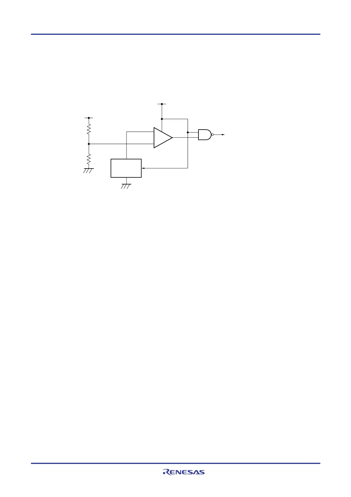
The block diagram of the power-on-reset circuit is shown in Figure 20-1.
Figure 20-1. Block Diagram of Power-on-reset Circuit
−
+
Reference
voltage
source
Internal reset signal
VDD
VDD
20.3 Operation of Power-on-reset Circuit
• An internal reset signal is generated on power application. When the supply voltage (V
DD) exceeds the detection
voltage (V
PDR = 1.51 V ±0.03 V), the reset status is released.
• The supply voltage (V
DD) and detection voltage (VPDR = 1.50 V ±0.03 V) are compared. When VDD < VPDR, the
internal reset signal is generated.
The timing of generation of the internal reset signal by the power-on-reset circuit and voltage detector is shown below.

 Loading...


