RL78/G13 CHAPTER 17 KEY INTERRUPT FUNCTION
R01UH0146EJ0100 Rev.1.00 852
Sep 22, 2011
17.3 Register Controlling Key Interrupt
(1) Key return mode register (KRM)
KRM register controls the KR0 to KR7 signals.
The KRM register can be set by a 1-bit or 8-bit memory manipulation instruction.
Reset signal generation clears this register to 00H.
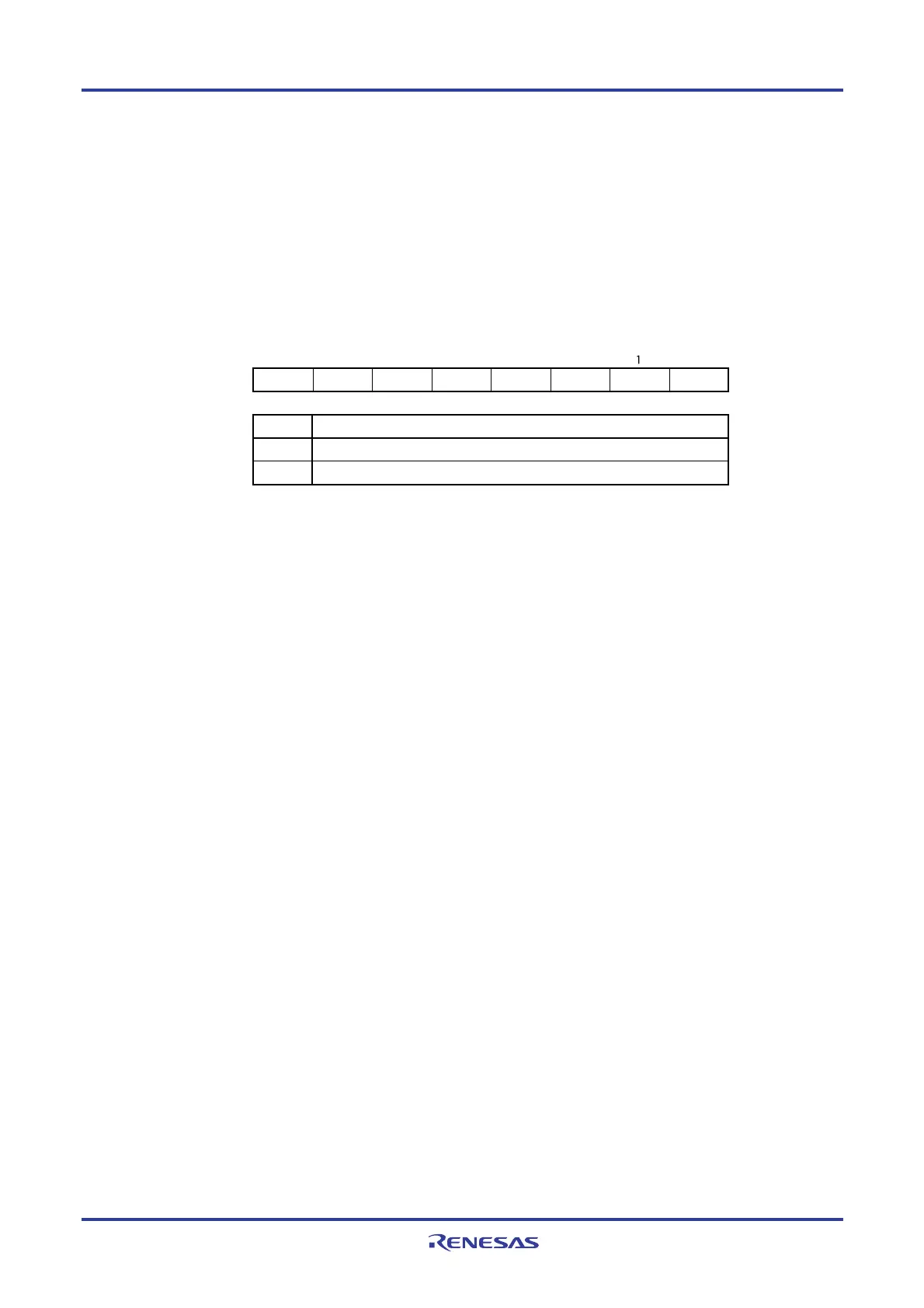
Figure 17-2. Format of Key Return Mode Register (KRM)
KRM7
Does not detect key interrupt signal
Detects key interrupt signal
KRMn
0
1
Key interrupt mode control
KRM KRM6 KRM5 KRM4 KRM3 KRM2 KRM1 KRM0
Address: FFF37H After reset: 00H R/W
Symbol
765432 0
Cautions 1. If any of the KRM0 to KRM7 bits used is set to 1, set bits 0 to 7 (PU70 to PU77) of the
corresponding pull-up resistor register 7 (PU7) to 1.
2. An interrupt will be generated if the target bit of the KRM register is set while a low level is being
input to the key interrupt input pin. To ignore this interrupt, set the KRM register after disabling
interrupt servicing by using the interrupt mask flag. Afterward, clear the interrupt request flag
and enable interrupt servicing after waiting for the key interrupt input low-level width (250 ns or
more).
3. The pins not used in the key interrupt mode can be used as normal ports.
Remarks 1. n = 0 to 7
2. KR0 to KR3: 40-, 44-pin products
KR0 to KR5: 48-pin products
KR0 to KR7: 52-, 64-, 80-, 100-, 128-pin products
 Loading...


