RL78/G13 CHAPTER 1 OUTLINE
R01UH0146EJ0100 Rev.1.00 38
Sep 22, 2011
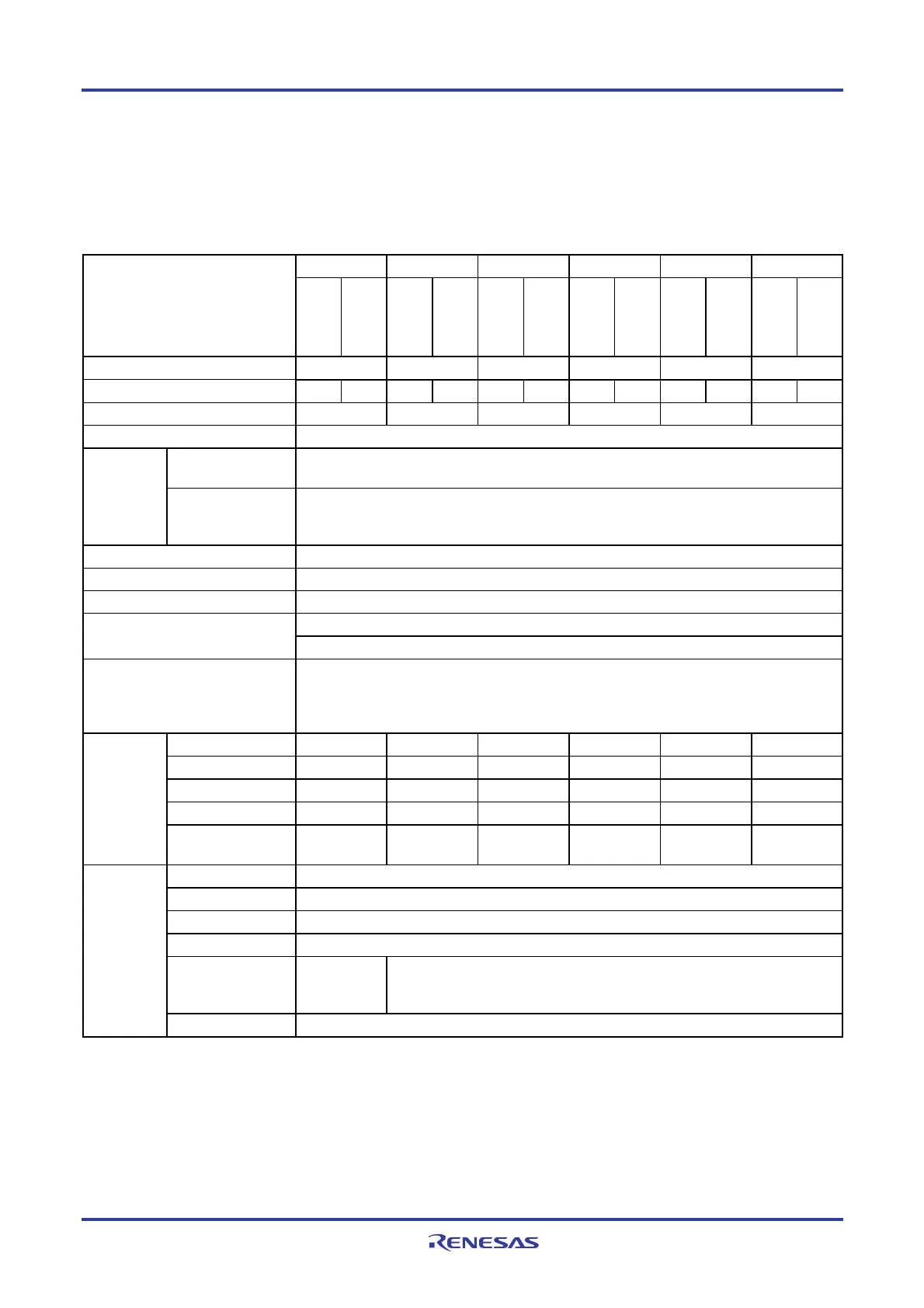
1.6 Outline of Functions
[20-pin, 24-pin, 25-pin, 30-pin, 32-pin, 36-pin products]
Caution This outline describes the functions at the time when Peripheral I/O redirection register (PIOR) is set
to 00H.
(1/2)
20-pin 24-pin 25-pin 30-pin 32-pin 36-pin Item
R5F1006x
R5F1016x
R5F1007x
R5F1017x
R5F1008x
R5F1018x
R5F100Ax
R5F101Ax
R5F100Bx
R5F101Bx
R5F100Cx
R5F101Cx
Code flash memory (KB) 16 to 64 16 to 64 16 to 64 16 to 128 16 to 128 16 to 128
Data flash memory (KB) 4
−
4
−
4
−
4 to 8
−
4 to 8
−
4 to 8
−
RAM (KB) 2 to 4
Note1
2 to 4
Note1
2 to 4
Note1
2 to 12
Note1
2 to 12
Note1
2 to 12
Note1
Memory space 1 MB
High-speed system
clock
X1 (crystal/ceramic) oscillation, external main system clock input (EXCLK)
1 to 20 MHz: V
DD = 2.7 to 5.5 V, 1 to 8 MHz: VDD = 1.8 to 2.7 V, 1 to 4 MHz: VDD = 1.6 to 1.8 V
Main system
clock
High-speed on-chip
oscillator
High-speed operation: 1 to 32 MHz (V
DD = 2.7 to 5.5 V), High-speed operation: 1 to 16 MHz (VDD =
2.4 to 5.5 V), Low-speed operation: 1 to 8 MHz (V
DD = 1.8 to 5.5 V), Low-voltage operation: 1 to 4
MHz (V
DD = 1.6 to 5.5 V)
Subsystem clock
−
Low-speed on-chip oscillator 15 kHz (TYP.): VDD = 1.6 to 5.5 V
General-purpose register 8 bits × 32 registers (8 bits × 8 registers × 4 banks)
0.03125
μ
s (High-speed on-chip oscillator: fIH = 32 MHz operation) Minimum instruction execution time
0.05
μ
s (High-speed system clock: fMX = 20 MHz operation)
Instruction set • Data transfer (8/16 bits)
• Adder and subtractor/logical operation (8/16 bits)
• Multiplication (8 bits × 8 bits)
• Rotate, barrel shift, and bit manipulation (Set, reset, test, and Boolean operation), etc.
I/O port Total 16 20 21 26 28 32
CMOS I/O 13 15 15 21 22 26
CMOS input 3 3 3 3 3 3
CMOS output
− −
1
− − −
N-ch open-drain I/O
(6 V tolerance)
−
2 2 2 3 3
16-bit timer 8 channels
Watchdog timer 1 channel
Timer
Real-time clock (RTC) 1 channel
Interval timer (IT) 1 channel
Timer output 3 channels
(PWM outputs:
2
Note 2
)
4 channels (PWM outputs: 3
Note 2
)
RTC output
−
Notes 1. In the case of the 4 KB, this is about 3 KB when the self-programming function and data flash function are
used. (For details, see CHAPTER 3)
2. The number of outputs varies, depending on the setting.

 Loading...


