RL78/G13 CHAPTER 22 SAFETY FUNCTIONS
R01UH0146EJ0100 Rev.1.00 903
Sep 22, 2011
22.2 Registers Used by Safety Functions
The safety functions use the following registers for each function.
Register Each Function of Safety Function
• Flash memory CRC control register (CRC0CTL)
• Flash memory CRC operation result register (PGCRCL)
Flash memory CRC operation function
(high-speed CRC)
• CRC input register (CRCIN)
• CRC data register (CRCD)
CRC operation function
(general-purpose CRC)
• RAM parity error control register (RPECTL) RAM parity error detection function
RAM guard function
SFR guard function
• Invalid memory access detection control register (IAWCTL)
Invalid memory access detection function
• Timer input select register 0 (TIS0) Frequency detection function
• A/D test register (ADTES) A/D test function
The content of each register is described in 22.3 Operation of Safety Functions.
22.3 Operation of Safety Functions
22.3.1 Flash memory CRC operation function (high-speed CRC)
The IEC60730 standard mandates the checking of data in the flash memory, and recommends using CRC to do it. The
high-speed CRC provided in the RL78/G13 can be used to check the entire code flash memory area during the
initialization routine. The high-speed CRC can be executed only when the program is allocated on the RAM and in the
HALT mode of the main system clock.
The main feature of this check is that it does not take a long time. (For example, it only takes 512
μ
s to check a 64 KB
flash memory using a 32 MHz clock.)
The CRC generator polynomial used complies with “X
16
+ X
12
+ X
5
+ 1” of CRC-16-CCITT.
The high-speed CRC operates in MSB first order from bit 31 to bit 0.
Remark The operation result is different between the high-speed CRC and the general CRC, because the general
CRC operates in LSB first order.
<Control register>
(1) Flash memory CRC control register (CRC0CTL)
This register is used to control the operation of the high-speed CRC ALU, as well as to specify the operation range.
The CRC0CTL register can be set by a 1-bit or 8-bit memory manipulation instruction.
Reset signal generation clears this register to 00H.
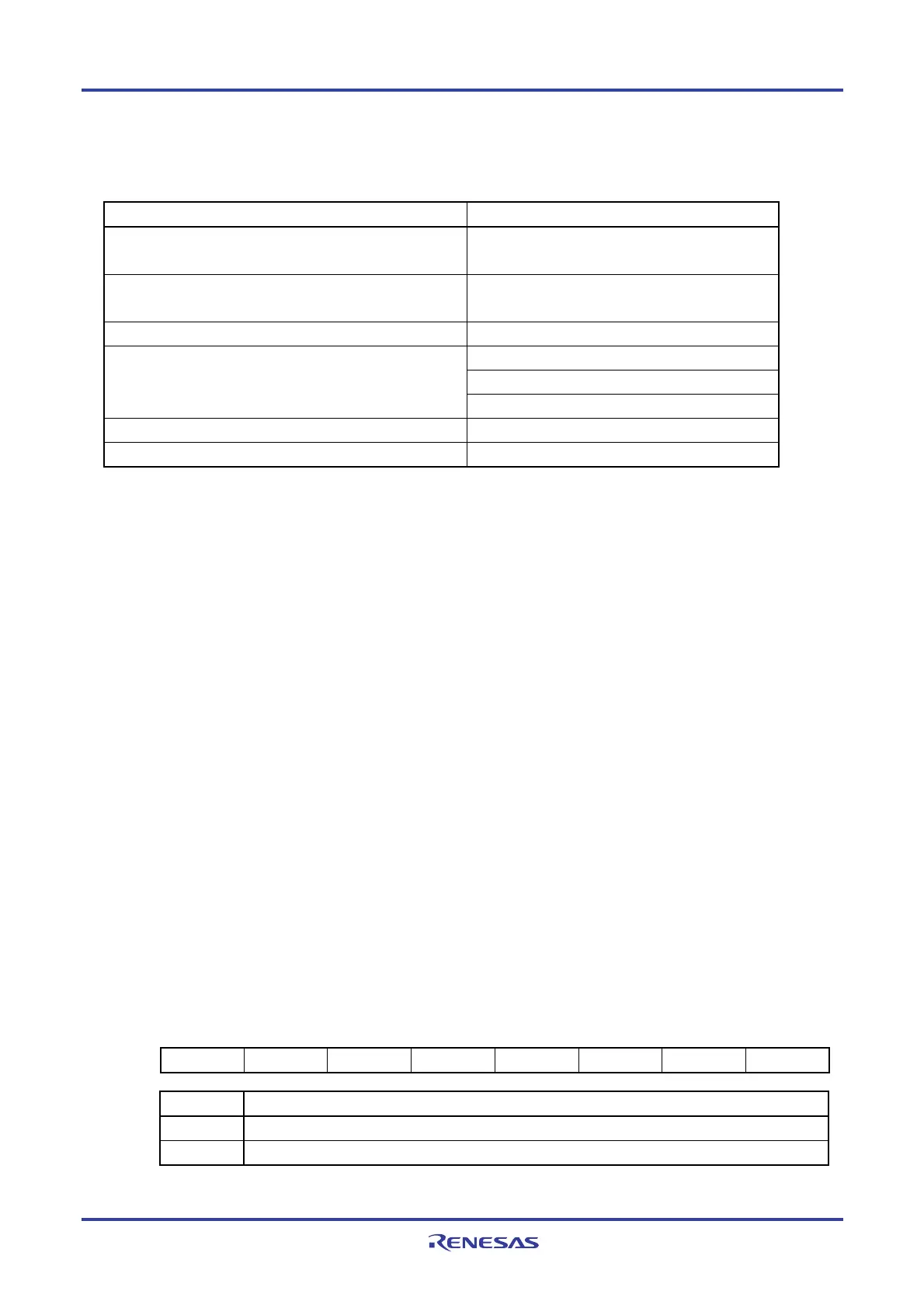
Figure 22-1. Format of Flash Memory CRC Control Register (CRC0CTL) (1/2)
Address: F02F0H After reset: 00H R/W
Symbol <7> 6 5 4 3 2 1 0
CRC0CTL CRC0EN 0 FEA5 FEA4 FEA3 FEA2 FEA1 FEA0
CRC0EN Control of CRC ALU operation
0 Stop the operation.
1 Start the operation according to HALT instruction execution.

 Loading...


