RL78/G13 CHAPTER 6 TIMER ARRAY UNIT
R01UH0146EJ0100 Rev.1.00 326
Sep 22, 2011
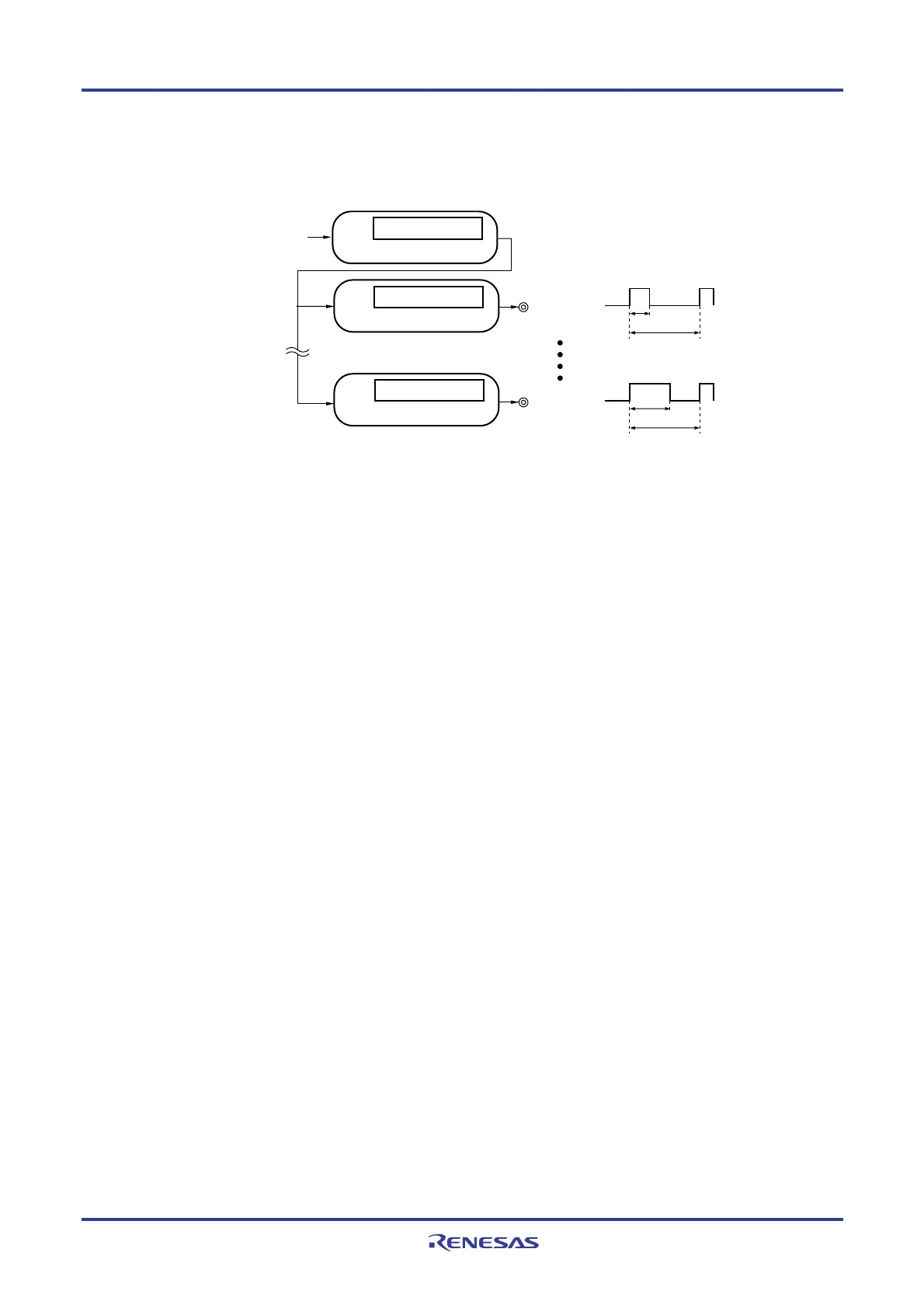
(3) Multiple PWM (Pulse Width Modulation) output
By extending the PWM function and using one master channel and two or more slave channels, up to seven types
of PWM signals that have a specific period and a specified duty factor can be generated.
Duty
Period
Interrupt signal (INTTMmn)
Duty
Period
Channel n (master)
Channel p (slave)
Channel q (slave)
Operation clock
Compare operation
Compare operation
Compare operation
Timer output
(TOmp)
Timer output
(TOmq)
Caution The following rules apply when using multiple channels simultaneously.
• Only an even-numbered channel (channel 0, 2, 4, …) can be specified as the master channel.
• Only channels with lower channel numbers than the master channel can be specified as slave
channels (multiple slave channels can be set).
For details about the rules of simultaneous channel operation function, see 6.4.1 Basic rules of
simultaneous channel operation function.
Remark m: Unit number (m = 0, 1), n: Channel number (n = 0 to 7),
p, q: Slave channel number (n < p < q ≤ 7)
6.1.3 8-bit timer operation function (channels 1 and 3 only)
The 8-bit timer operation function makes it possible to use a 16-bit timer channel in a configuration consisting of two 8-
bit timer channels. This function can only be used for channels 1 and 3.
Caution There are several rules for using 8-bit timer operation function.
For details, see 6.4.2 Basic rules of 8-bit timer operation function (channels 1 and 3 only).
 Loading...


