RL78/G13 CHAPTER 27 BCD CORRECTION CIRCUIT
R01UH0146EJ0100 Rev.1.00 955
Sep 22, 2011
CHAPTER 27 BCD CORRECTION CIRCUIT
27.1 BCD Correction Circuit Function
The result of addition/subtraction of the BCD (binary-coded decimal) code and BCD code can be obtained as BCD
code with this circuit.
The decimal correction operation result is obtained by performing addition/subtraction having the A register as the
operand and then adding/ subtracting the BCD correction result register (BCDADJ).
27.2 Registers Used by BCD Correction Circuit
The BCD correction circuit uses the following registers.
• BCD correction result register (BCDADJ)
(1) BCD correction result register (BCDADJ)
The BCDADJ register stores correction values for obtaining the add/subtract result as BCD code through
add/subtract instructions using the A register as the operand.
The value read from the BCDADJ register varies depending on the value of the A register when it is read and those
of the CY and AC flags.
The BCDADJ register is read by an 8-bit memory manipulation instruction.
Reset input sets this register to undefined.
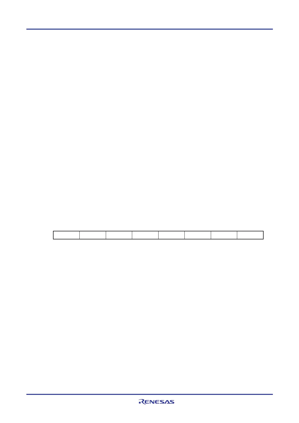
Figure 27-1. Format of BCD Correction Result Register (BCDADJ)
Address: F00FEH After reset: undefined R
Symbol 7 6 5 4 3 2 1 0
BCDADJ

 Loading...


