RL78/G13 CHAPTER 5 CLOCK GENERATOR
R01UH0146EJ0100 Rev.1.00 287
Sep 22, 2011
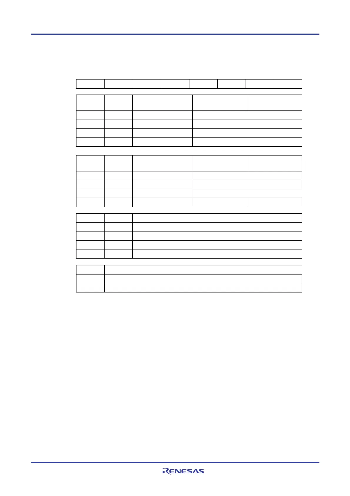
Figure 5-2. Format of Clock Operation Mode Control Register (CMC)
Address: FFFA0H After reset: 00H R/W
Symbol 7 6 5 4 3 2 1 0
CMC EXCLK OSCSEL EXCLKS OSCSELS 0 AMPHS1 AMPHS0 AMPH
EXCLK OSCSEL High-speed system clock
pin operation mode
X1/P121 pin X2/EXCLK/P122 pin
0 0 Input port mode Input port
0 1 X1 oscillation mode Crystal/ceramic resonator connection
1 0 Input port mode Input port
1 1 External clock input mode Input port External clock input
EXCLKS OSCSELS Subsystem clock pin
operation mode
XT1/P123 pin XT2/EXCLKS/P124 pin
0 0 Input port mode Input port
0 1 XT1 oscillation mode Crystal resonator connection
1 0 Input port mode Input port
1 1 External clock input mode Input port External clock input
AMPHS1 AMPHS0 XT1 oscillator oscillation mode selection
Note
0 0 Low power consumption oscillation (default) Oscillation margin: Medium
0 1 Normal oscillation Oscillation margin: high
1 0 Ultra-low power consumption oscillation Oscillation margin: Low
1 1 Setting prohibited
AMPH Control of X1 clock oscillation frequency
0 1 MHz ≤ fX ≤ 10 MHz
1 10 MHz < fX ≤ 20 MHz
Note As the XT oscillator becomes oscillation mode with lower power consumption, then its oscillation
margin becomes smaller.
Cautions 1. The CMC register can be written only once after reset release, by an 8-bit memory
manipulation instruction.
2. After reset release, set the CMC register before X1 or XT1 oscillation is started as set
by the clock operation status control register (CSC).
3. Be sure to set the AMPH bit to 1 if the X1 clock oscillation frequency exceeds 10 MHz.
4. When the CMC register is used at the default value (00H), be sure to set 00H to this
register after reset release in order to prevent malfunctioning during a program loop.
5. The XT1 oscillator is a circuit with low amplification in order to achieve low-power
consumption. Note the following points when designing the circuit.
• Pins and circuit boards include parasitic capacitance. Therefore, perform
oscillation evaluation using a circuit board to be actually used and confirm that
there are no problems.
• When using the ultra-low power consumption oscillation (AMPHS1, AMPHS0 = 1,
0) as the mode of the XT1 oscillator, use the recommended resonators described
in CHAPTER 29 ELECTRICAL SPECIFICATIONS.
(Cautions and Remark are given on the next page.)
<R>
<R>

 Loading...


