RL78/F13, F14 CHAPTER 20 EVENT LINK CONTROLLER (ELC) (RL78/F14 Only)
R01UH0368EJ0210 Rev.2.10 1470
Dec 10, 2015
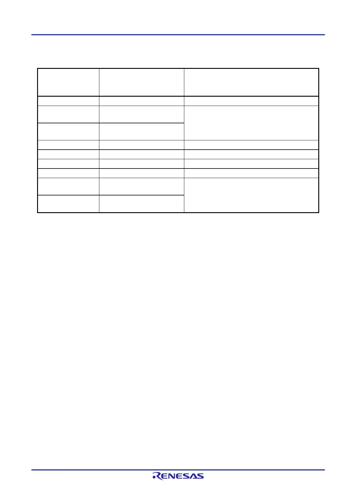
Table 20-3. Correspondence Between Values Set to ELSELRn (n = 00 to 25) Registers and Operation
of Link Destination Peripheral Functions at Reception
Bits ELSELRn3 to
ELSELRn0 in ELSELRn
Register
Link Destination Peripheral Function
Operation When Receiving Event
0001B
A/D converter A/D conversion starts
0010B
Timer input of timer array unit 0
channel 0
Notes 1 and 2
Delay counter, input pulse interval measurement, external
event counter
0011B
Timer input of timer array unit 0
channel 1
Notes 1 and 2
0100B
Timer RJ0 Count source
0101B
Timer RD0 TRDIOD0 input capture, pulse output cutoff
0110B
Timer RD1 TRDIOD1 input capture, pulse output cutoff
0111B
DA0
Note 3
Real-time output
1000B
Timer input of timer array unit 0
channel 2
Notes 1 and 2
Delay counter, input pulse interval measurement, external
event counter (Group E products only)
1001B
Timer input of timer array unit 0
channel 3
Notes 1 and 2
Notes 1. To select the timer input of timer array unit 0 channel m as the link destination peripheral function, first set the
operating clock for channel m to fCLK using timer clock select register 0 (TPS0), and then set the timer output
used for channel m to an event input signal from the ELC using timer input select register 0 (TIS0).
2. Before selecting the timer input of timer array unit 0 channel m as the link destination peripheral function, set
the noise filter of the corresponding link destination channel in the timer array unit 0 to OFF (set the TNFEN0m
bit to 0) by using the noise filter enable register 1 (NFEN1).
3. When entering the STOP status while the real-time output event mode for D/A conversion is enabled, disable
linking of ELC events before entering STOP.
Remark m = 0, 3

 Loading...


