RL78/F13, F14 CHAPTER 6 TIMER ARRAY UNIT
R01UH0368EJ0210 Rev.2.10 530
Dec 10, 2015
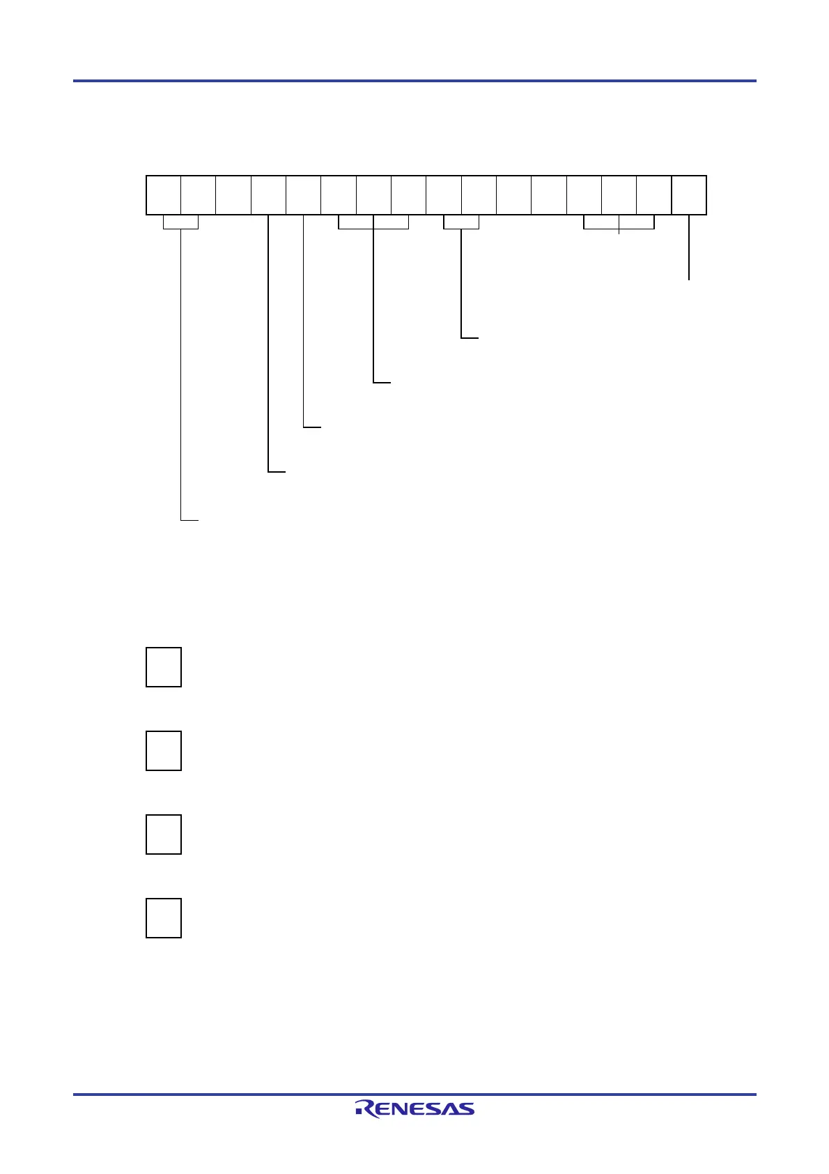
Figure 6-75. Example of Set Contents of Registers When PWM Function (Slave Channel) Is Used
(a) Timer mode register mp (TMRmp)
15 14 13 12 11 10 9 8 7 6 5 4 3 2 1 0
TMRmp
CKSmp1
1/0
CKSmp0
1/0
0
CCSmp
0
M/S
Note
0
STSmp2
1
STSmp1
0
STSmp0
0
CISmp1
0
CISmp0
0
0
0
MDmp3
1
MDmp2
0
MDmp1
0
MDmp0
1
Operation mode of channel p
100B: One-count mode
Start trigger during operation
1: Trigger input is valid.
Selection of TImp pin input edge
00B: Sets 00B because these are not used.
Start trigger selection
100B: Selects INTTMmn of master channel.
Setting of MASTERmp or SPLITmp bit
0: Slave channel.
Count clock selection
0: Selects operation clock (f
MCK).
Operation clock (f
MCK) selection
00B: Selects CKm0 as operation clock of channel p.
01B: Selects CKm2 as operation clock of channel p.
10B: Selects CKm1 as operation clock of channel p.
11B: Selects CKm3 as operation clock of channel p.
* Make the same setting as master channel.
(b) Timer output register m (TOm)
Bit p
TOm
TOmp
1/0
0: Outputs 0 from TOmp.
1: Outputs 1 from TOmp.
(c) Timer output enable register m (TOEm)
Bit p
TOEm
TOEmp
1/0
0: Stops the TOmp output operation by counting operation.
1: Enables the TOmp output operation by counting operation.
(d) Timer output level register m (TOLm)
Bit p
TOLm
TOLmp
1/0
0: Positive logic output (active-high)
1: Negative logic output (active-low)
(e) Timer output mode register m (TOMm)
Bit p
TOMm
TOMmp
1
1: Sets the slave channel output mode.
Note TMRm5, TMRm7: Fixed to 0
TMRm1, TMRm3: SPLITmp bit
Remarks 1. m: Unit number (m = 0, 1), n: Master channel number (n = 0, 2, 4, 6)
p: Slave channel number (n < p ≤ 7)
2. Unit 1 is not provided in the Group A products.
Channels 7 to 4 of unit 1 are not provided in the Group B, C, and D products.

 Loading...


