Image Adjustment
191
Adjustment Procedure
1. Enter SP2-109-003.
2. Print out the test pattern (14: 1-dot trimming pattern) with SP2-109-003.
• Registration can change slightly as shown on the previous page. Print some pages of the 1-dot
trimming pattern for steps 3 and 4. Then average the leading edge and side-to-side registration
values, and adjust each SP mode.
3. Do the leading edge registration adjustment.
1) Check the leading edge registration and adjust it with SP1-001.
2) Select the adjustment conditions (paper type and process line speed).
3) Input the value. Then press [#].
4) Generate a trim pattern to check the leading edge adjustment.
4. Do the side-to-side registration adjustment.
1) Check the side-to-side registration and adjust it with SP1-002.
2) Select the adjustment conditions (paper feed station).
3) Input the value. Then press [#].
4) Generate a trim pattern to check the side-to-side registration adjustment.
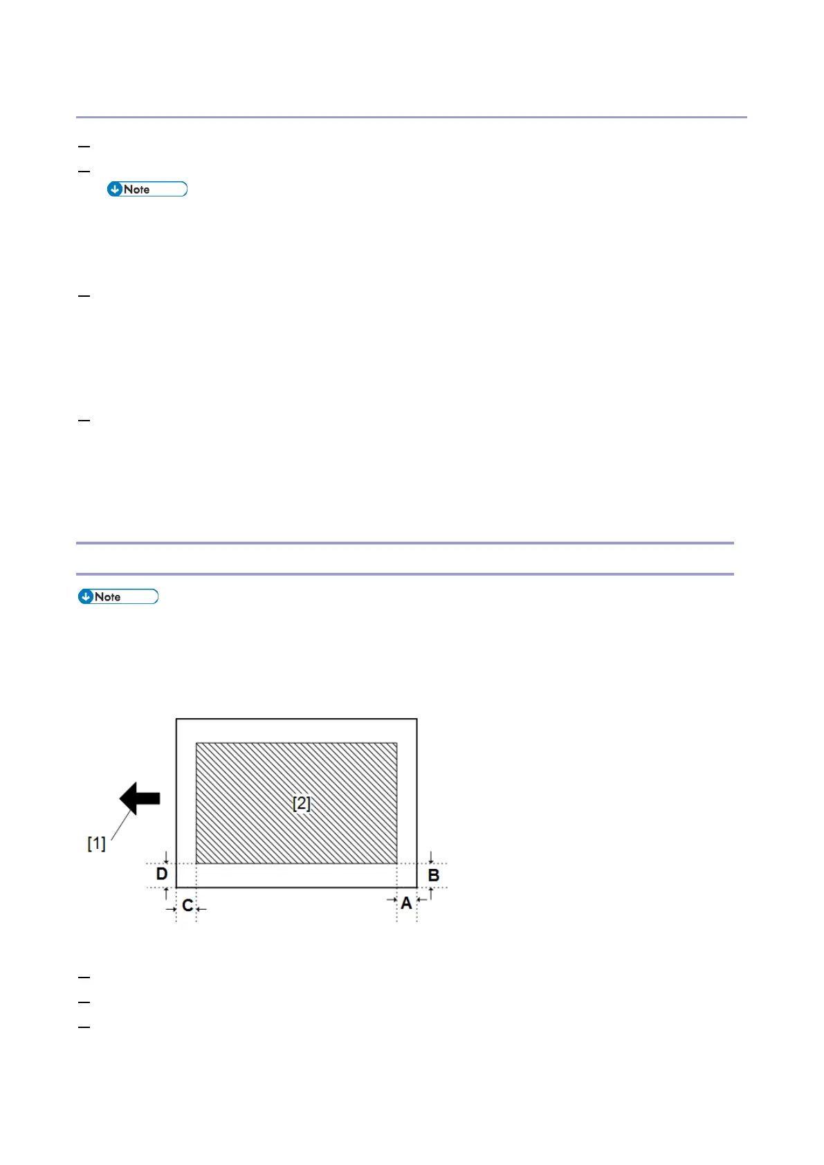
Erase Margin Adjustment
• After adjusting the Leading Edge Registration and Side Registration settings (see the previous
section), do the Erase Margin Adjustment. To do this, check the values of Margins A and B.
• If they are not within the specifications (see below), then adjust A and B with SP2-103-001 to -004 as
explained below. Then check Margins C and D again.
[1]: Feed direction, [2]: Image area
1. Enter the SP mode.
2. Print out the test pattern (14: 1-dot trimming pattern) with SP2-109-003.
3. Check the erase margin A and B. Adjust them with SP2-103-001 to -004 if necessary.
• Leading edge: 0.0 to 9.9 mm (default: 4.2 mm)
• Side-to-side: 0.0 to 9.9 mm (default: 2.0 mm)
 Loading...