Mounting position, mounting clearances
6.2 SITOP UPS1100
SITOP UPS1600 / UPS1100
Manual, 04.2017, A5E37775406-8-76
201
Standard mounting position
The device is suitable for the direct wall mounting. Devices 6EP4131-0GB00-0AY0 (1.2 Ah),
6EP4132-0GB00-0AY0 (2.5 Ah), 6EP4133-0GB00-0AY0 (3.2 Ah) and 6EP4133-0JB00-
0AY0 (5 Ah) can also be snapped onto a standard mounting rail TH35×15 (EN 60715), and
device 6EP4131-0GB00-0AY0 (1.2 Ah), also onto a standard mounting rail TH35×7.5
(EN 60715). It should also be mounted at the coolest point in the control cabinet (e.g. in the
lower part of the control cabinet). The device must be mounted vertically in such a way that
the terminals are at the bottom.
No clearance is required at the side.
Note
In the case of mounting positions that deviate from the standard mounting position, reduced
mechanical resistance of the devices against vibration and shock must be expected.
Particularly when installing on a vertically fastened standa
rd mounting rail, additional
measures may be required, e.g. to prevent the device from slipping on the rail.
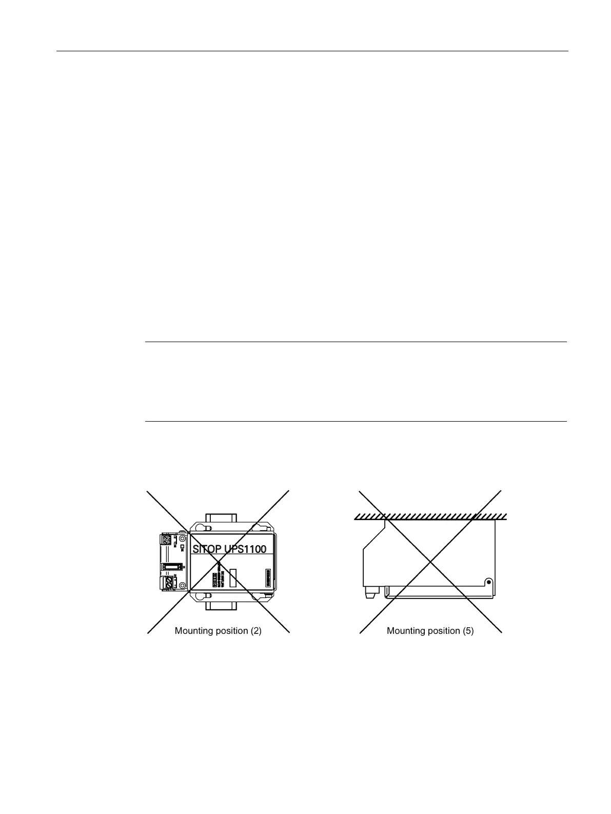
All mounting positions have been released, except the following:
For UPS1100 1.2 Ah: Mounting position (2) (see the following diagram)
all other UPS1100: Mounting position (5) (see the following diagram)
Figure 6-19 Mounting positions forbidden for the UPS1100
 Loading...