Description, device design, dimension drawing
2.2 Connections and terminal designation
SITOP UPS1600 / UPS1100
22 Manual, 04.2017, A5E37775406-8-76
REL1 (changeover contact):
Energized state: Normal operation
Quiescent state: Buffer mode or off
2 -
3 OK
Ready for buffer operation / alarm
REL2 (changeover contact):
Energized state: Buffer mode is possible
Quiescent state: Not ready for buffering
Cycle 0.25 Hz: Defective battery
6 RDY TO BUFFER
REL3 (NO contact):
Energized state: Buffering of the selected buffer time is possible,
8 -
On/Off (buffer operation permitted/prevented)
Battery communication or charging current setting
Battery supply or charging current setting
Interrupt (interruption of the output voltage)
Relay contact: Contact rating, max. AC 30 V/0.5 A; DC 60 V/0.3 A; DC 30 V/1 A
The jumper (4a) (see Figure Signal connector (Page 21)) between pin 9 and 10 is necessary
to operate the device in buffer mode.
Delivery state: Jumper between pin 9 and 10
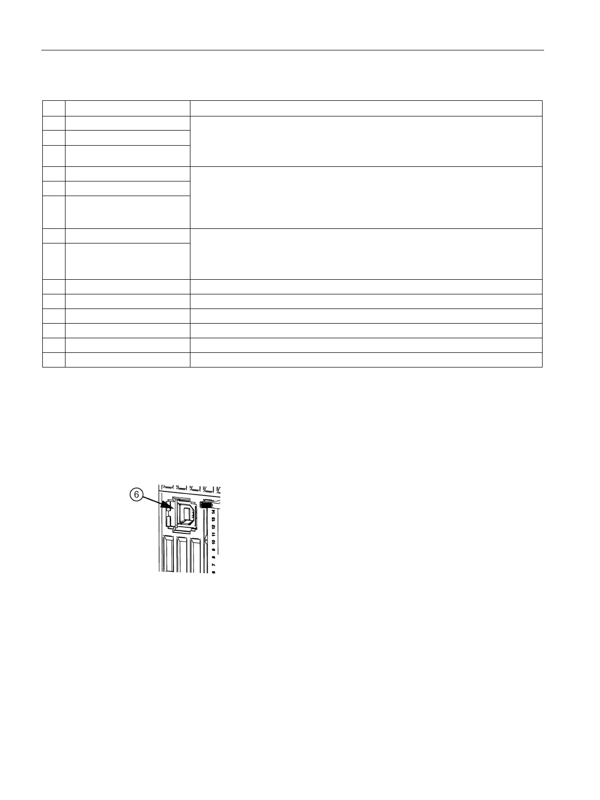
Figure 2-7 USB port
The USB interface (type B) ⑥ fully conforms to the USB 2.0 standard (12 MBd). Strain relief
(see Section USB connector (Page 189)) is implemented using a defined cable/connector
(Y-Con USB - Yamaichi).
 Loading...