Description, device design, dimension drawing
2.2 Connections and terminal designation
SITOP UPS1600 / UPS1100
24 Manual, 04.2017, A5E37775406-8-76
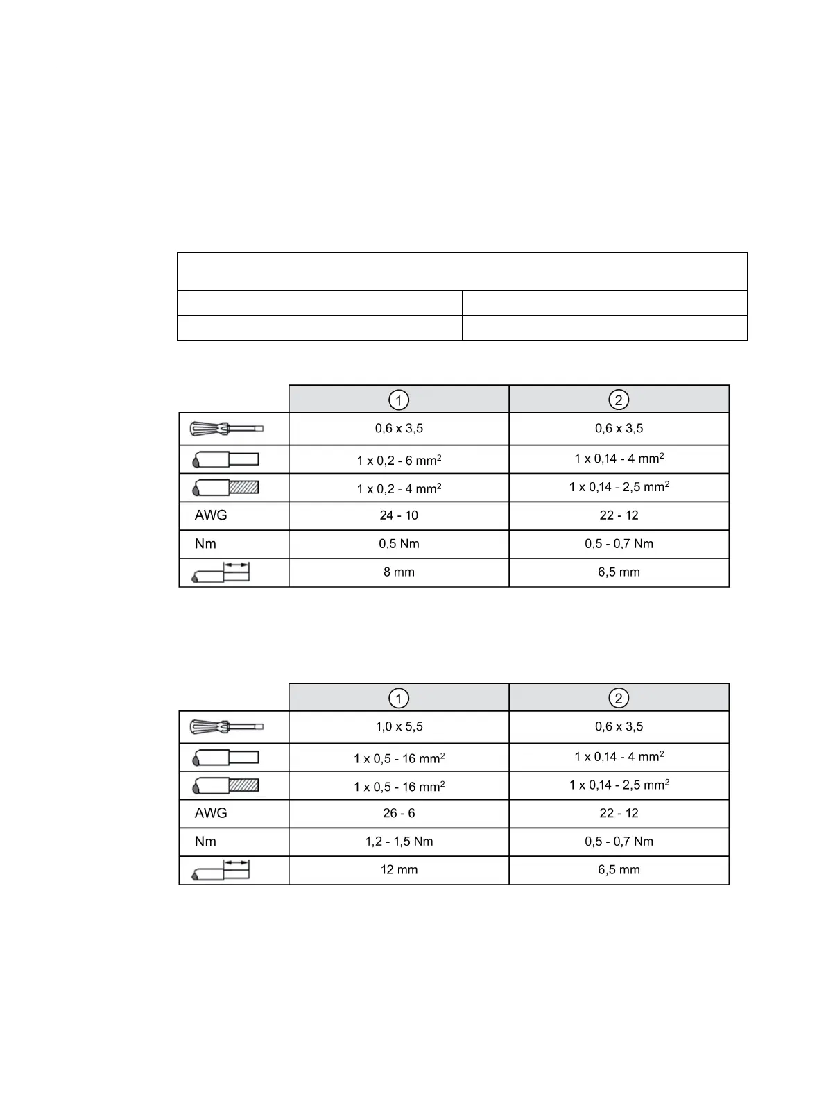
Input terminals ① and signal terminal ② can be used to establish the connection to
SITOP UPS1600. (also see Chapter Installation (Page 203)).
Connections and terminal designations (see Figure 2-2 SITOP UPS1100 design (example 6EP4133-
0GB00-0AY0) (Page 18))
DC input +, -
One screw terminal each
Signal terminal 1, 2
One screw terminal each
Figure 2-9 Terminal data for 6EP4131-0GB00-0AY0, 6EP4132-0GB00-0AY0, 6EP4133-0GB00
and 6EP4133-0JB00-0AY0
Figure 2-10 Terminal data for 6EP4134-0GB00-0AY0 and 6EP4135-0GB00-0AY0
 Loading...