Description, device design, dimension drawing
2.3 Operator controls
SITOP UPS1600 / UPS1100
Manual, 04.2017, A5E37775406-8-76
25
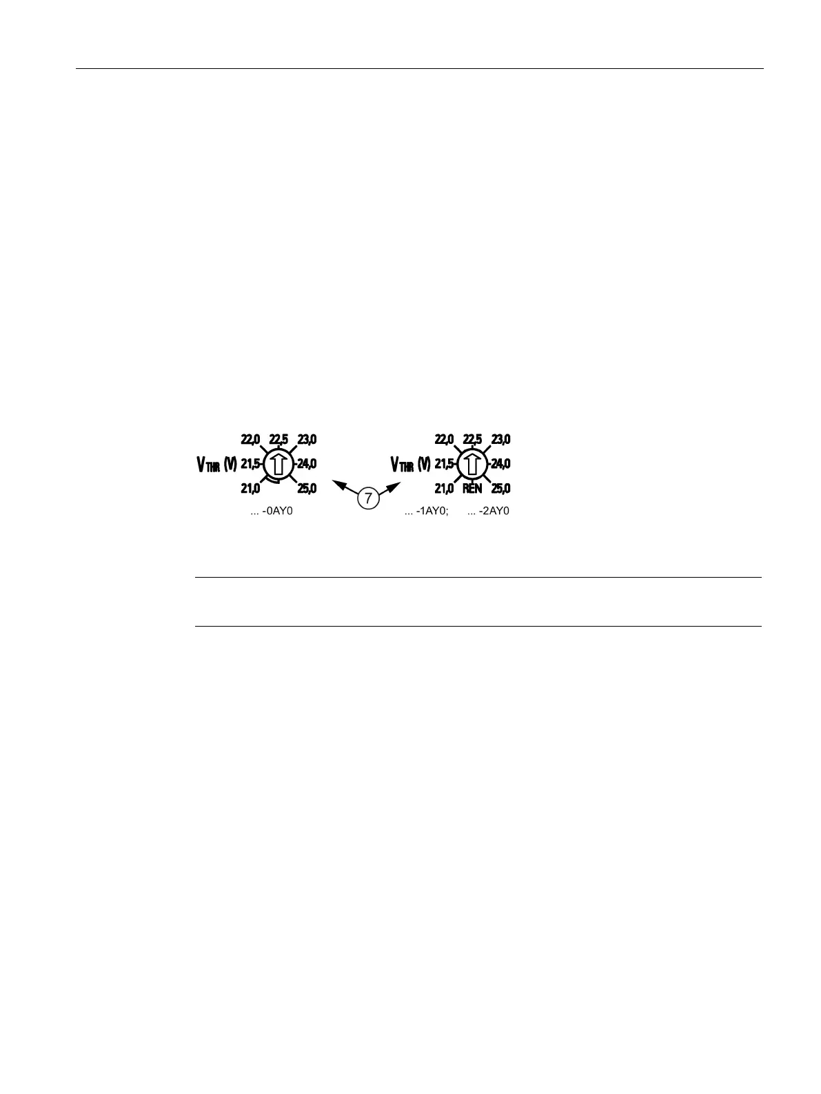
Rotary coding switch, switch-in threshold
The switch-in threshold can be set using the rotary coding switch ⑦ on the device front
between 21.0 V and 25.0 V (21 - 21.5 - 22 - 22.5 - 23 - 24 - 25 volt). The delivery state is
22.5 V
For devices with an interface (…-1AY0, …-2AY0), the coding switch has an additional REN
position. If this is selected, the software settings (for the switch-in threshold and the backup
time) apply rather than the hardware settings. In the switch position REN, the connection
X2.13 (INTERRUPT - reset after buffer operation) of the signal terminal (see Section Signal
terminal (Page 21)) has no effect.
Figure 2-11 Rotary coding switch, switch-in threshold
Note
It is only permissible to operate the rotary switch using an insulated screwdriver.
For notes on actuating the rotary coding switch (screwdriver, torque), see Figure 2-3
Terminal data SITOP UPS1600 10 A, 20 A (Page 20).
Rotary coding switch, backup time
The buffer time is set using the rotary coding switch ⑧ on the device front between 30
seconds and MAX in steps of 0.5 minute (30 s), 1 minute, 2 minutes, 5 minutes, 10 minutes,
20 minutes and MAX. The MAX setting means that buffering is realized for as long as
possible. The device only shuts down when the battery has discharged down to the stop
buffering voltage (factory setting, 18.5 V). Delivery state is MAX
The rotary coding switch has an additional setting OFF (see following diagram). If this is
selected and the additional threshold rotary coding switch is not set to REN, then buffering is
deactivated.
If the buffer time is to be set using the software (only for devices with an interface (…-1AY0,
…-2AY0)) (possible setting range, see Section Parameterizing SITOP UPS1600 (Page 77)),
the rotary coding switch for the connection threshold must be set to REN (see Section
Rotary coding switch, switch-in threshold (Page 25)).
 Loading...