4.5.8 Calibrating the electrical tool probe
If you want to measure your tools automatically, you must first determine the position of the
tool probe on the machine table with reference to the machine zero.
Tool probes are typically shaped like a cube or a cylindrical disk. Install the tool probe in the
working area of the machine (e.g on the machine table) and align it relative to the machining
axes.
You must use a mill-type calibration tool to calibrate the tool probe. You must enter the length
and radius/diameter of the calibration tool in the tool list beforehand.
Calibration of a tool probe with rotation
To compensate radial eccentricity of the spindle or position deviations of the calibrating tool
when calibrating the tool probe, you have the option to calibrate the tool probe with rotation.
This entails more exact calibration values of the tool probe and thus more exact measuring
values.
During calibration, the probe is withdrawn after the first probing, the spindle is rotated by 180°
and probing repeated. A mean value of two values is then determined and entered.
Note
Setting the protection level
The "Calibrate probe" function is only available if an adequate level of protection is set.
Please refer to the machine manufacturer's specifications.
Procedure
1. Move the calibration tool until it is approximately over the center of the
measuring surface of the tool probe.
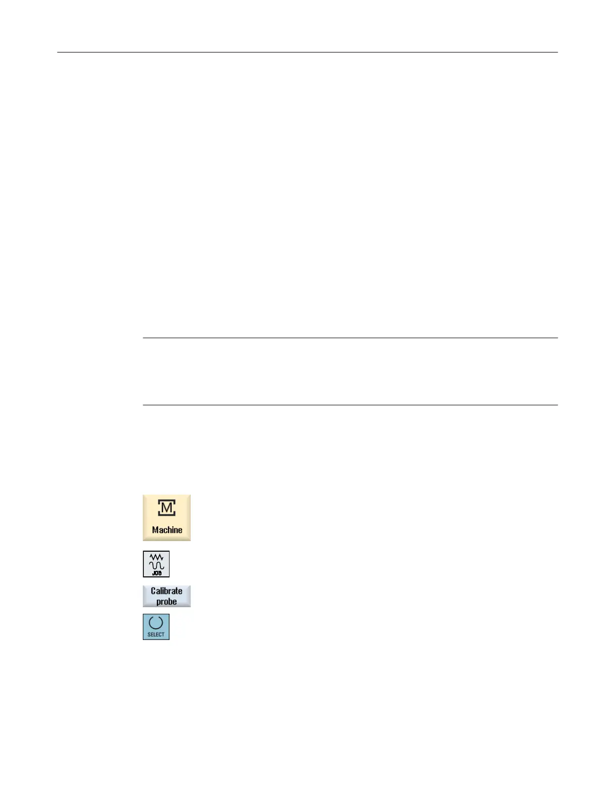
2. Select operating mode "JOG" in the "Machine" operating area and press
the "Measure tool" softkey.
3. Press the "Calibrate probe" softkey.
4. Choose whether you want to calibrate the length only, or the length and
the diameter.
Setting up the machine
4.5 Measure tool
Milling
Operating Manual, 08/2018, 6FC5398-7CP41-0BA0 107

 Loading...


