9.3 Fundamentals
9.3.1 Machining planes
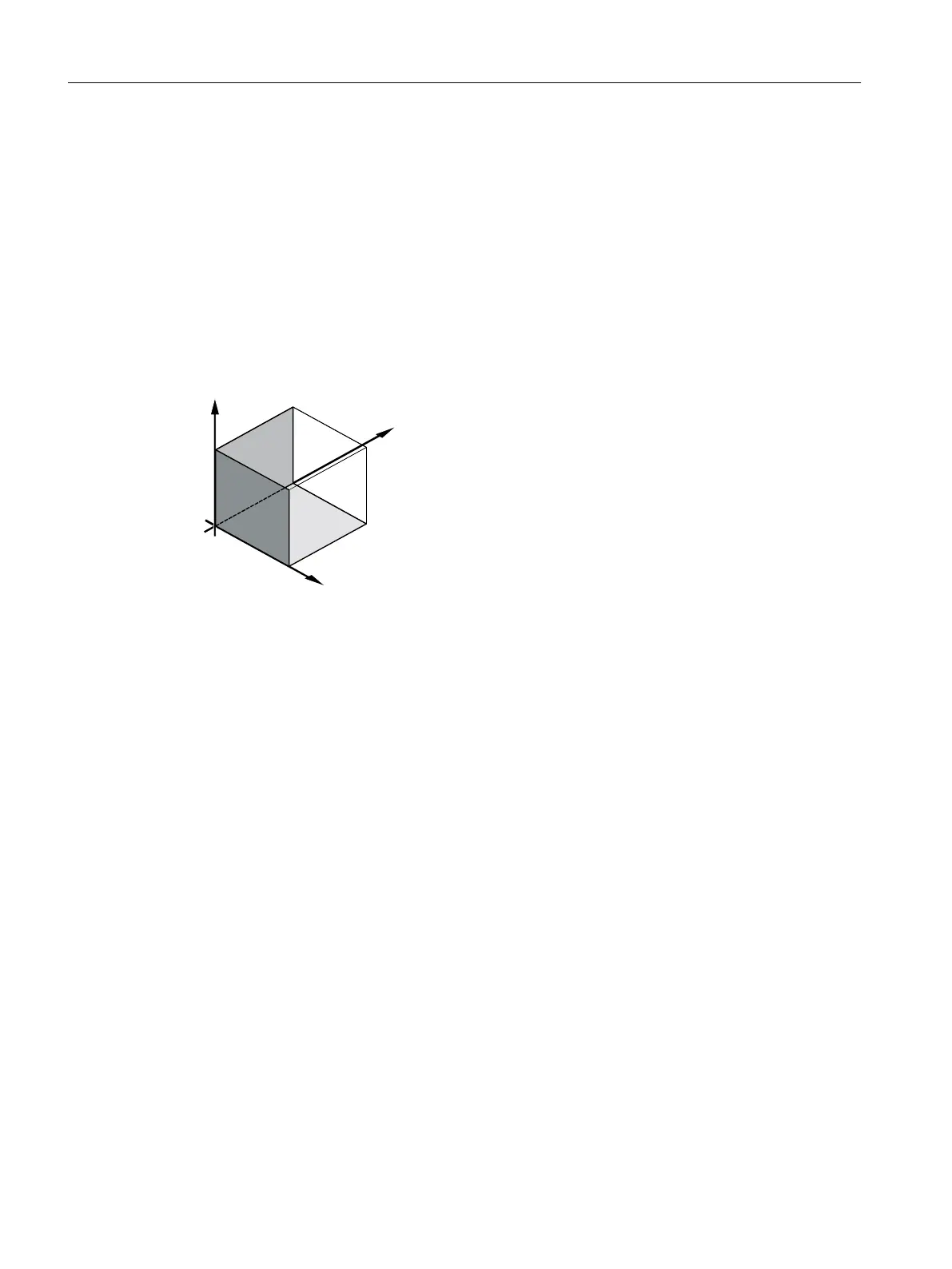
A plane is defined by means of two coordinate axes. The third coordinate axis (tool axis) is
perpendicular to this plane and determines the infeed direction of the tool (e.g. for 2½-D
machining).
When programming, it is necessary to specify the working plane so that the control system
can calculate the tool offset values correctly. The plane is also relevant to certain types of
circular programming and polar coordinates.
Working planes
Working planes are defined as follows:
Plane Tool axis
X/Y G17 Z
Z/X G18 Y
Y/Z G19 X
9.3.2 Polar coordinates
The rectangular coordinate system is suitable in cases where dimensions in the production
drawing are orthogonal. For workpieces dimensioned with arcs or angles, it is better to define
positions using polar coordinates. This is possible if you are programming a straight line or a
circle.
Polar coordinates have their zero point at the "pole".
Creating a ShopMill program
9.3 Fundamentals
Milling
324 Operating Manual, 08/2018, 6FC5398-7CP41-0BA0

 Loading...


