EasyManuals Logo
Home>Siemens>Control Systems>SINUMERIK 840DE SL

Siemens SINUMERIK 840DE SL User Manual

Siemens SINUMERIK 840DE SL
940 pages
To Next Page IconTo Next Page
To Previous Page IconTo Previous Page
Page #325 background imageLoading...
Page #325 background image
Example
3ROH


r
r
3
3
<
;


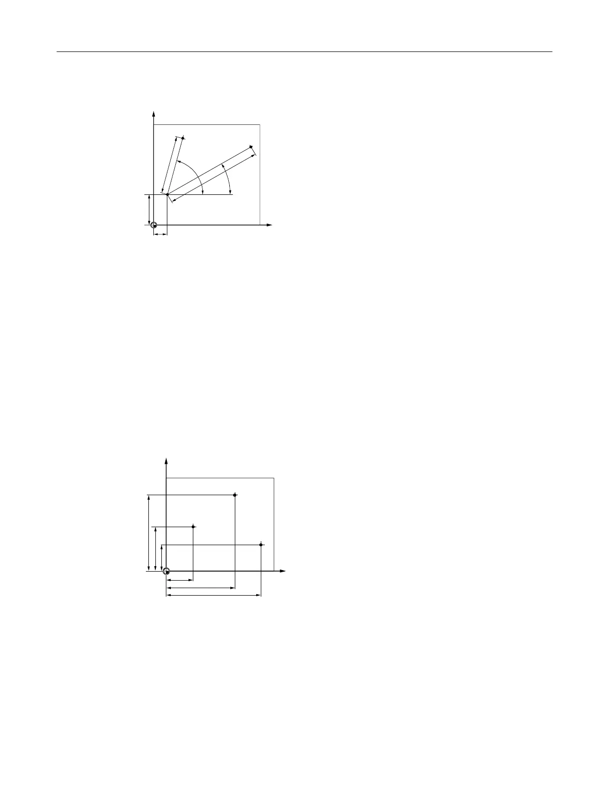
Points P1 and P2 can then be described – with reference to the pole – as follows:
P1: Radius =100 / angle =30°
P2: Radius =60 / angle =75°
9.3.3 Absolute and incremental dimensions
Absolute dimensions
With absolute dimensions, all the position specifications refer to the currently valid zero point.
Applied to tool movement this means: The absolute dimension data defines the position, to
which the tool is to travel.
Example



3
3
3



<
;
The position data points P1 to P3 in absolute dimensions relative to the zero point are the
following:
P1: X20 Y35
P2: X50 Y60
P3: X70 Y20
Creating a ShopMill program
9.3 Fundamentals
Milling
Operating Manual, 08/2018, 6FC5398-7CP41-0BA0 325

Table of Contents

Other manuals for Siemens SINUMERIK 840DE SL

Questions and Answers:

Question and Answer IconNeed help?

Do you have a question about the Siemens SINUMERIK 840DE SL and is the answer not in the manual?

Siemens SINUMERIK 840DE SL Specifications

General IconGeneral
BrandSiemens
ModelSINUMERIK 840DE SL
CategoryControl Systems
LanguageEnglish

Related product manuals