23.5.2 Structure of the user interface
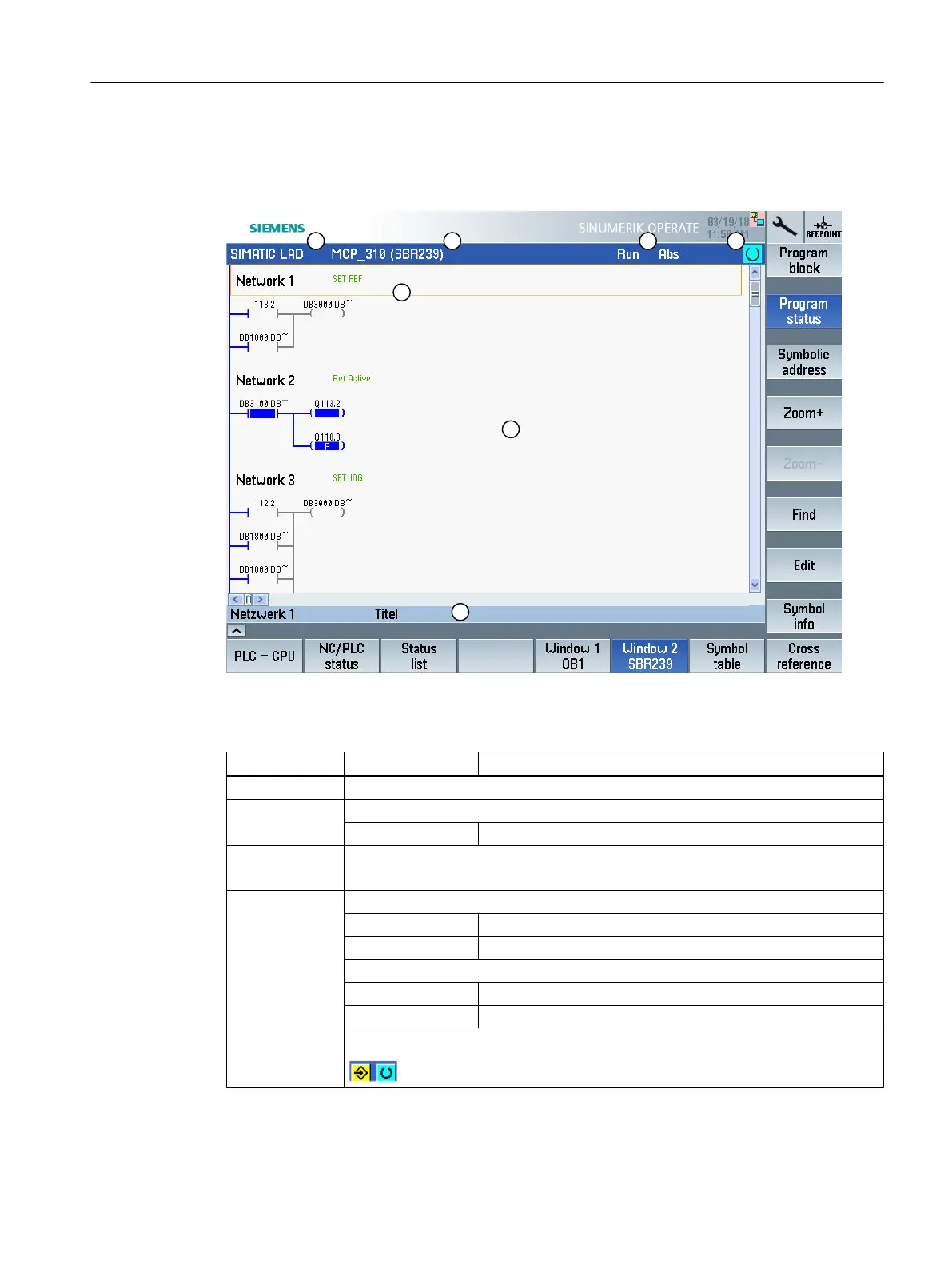
The following figure shows the user interface.
Figure 23-1 Screen layout
Table 23-1 Key to screen layout
Screen element Display Meaning
1 Application area
2 Supported PLC program language "LAD"
LAD* Program change exists
3 Name of the active program block
Representation: Symbolic name (absolute name)
4 Program status
Run Program is running
Stop Program is stopped
Status of the application area
Sym Symbolic representation
Abs Absolute representation
5 Display of the active keys (<INPUT>, <SELECT>)
Edit PLC user program (828D only)
23.5 View of the program blocks
Milling
Operating Manual, 08/2018, 6FC5398-7CP41-0BA0 907

 Loading...


