Parameter Description Unit
Machining
direction
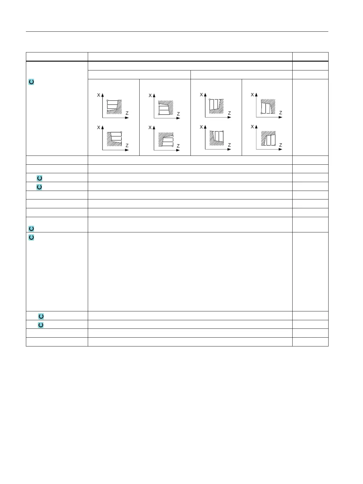
Stock removal direction (longitudinal or transverse) in the coordinate system
Parallel to the Z axis (longitudinal) Parallel to the X axis (transverse)
outside inside outside inside
X0 Reference point in X ∅ (abs, always diameter) mm
Z0 Reference point in Z (abs) mm
X1 End point X (abs) or end point X in relation to X0 (inc) mm
Z1 End point Z ∅ (abs) or end point Z in relation to Z0 (inc) mm
D Maximum depth infeed – (not for finishing) mm
UX Finishing allowance in X – (not for finishing) mm
UZ Finishing allowance in Z – (not for finishing) mm
FS1...FS3 or R1...R3 Chamfer width (FS1...FS3) or rounding radius (R1...R3) - (not for
stock removal 1)
mm
Parameter selection of intermediate point
The intermediate point can be determined through position specification or angle.
The following combinations are possible - (not for stock removal 1 and 2)
● XM ZM
● XM α1
● XM α2
● α1 ZM
● α2 ZM
● α1 α2
XM Intermediate point X ∅ (abs) or intermediate point X in relation to X0 (inc) mm
ZM Intermediate point Z (abs or inc) mm
α1 Angle of the 1st edge Degrees
α2 Angle of the 2nd edge Degrees
* Unit of feedrate as programmed before the cycle call
10.4.3 Groove (CYCLE930)
Function
You can use the "Groove" cycle to machine symmetrical and asymmetrical grooves on any
straight contour elements.
Programming technological functions (cycles)
10.4 Turning - milling/turning machine
Milling
518 Operating Manual, 08/2018, 6FC5398-7CP41-0BA0

 Loading...


